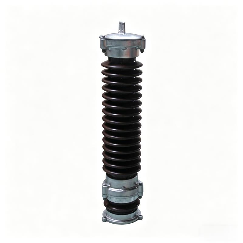
Y5WZ-51-134 Zinc Oxide Arrester, 35kV Metal Oxide Arrester
Y5WZ-51-134 zinc oxide arrester is a metal oxide arrester widely used in 35kV voltage class power systems, providing reliable overvoltage protection for various electrical equipment.
I. Overview
Arresters are the basis for insulation coordination of various electrical equipment in power systems (transformers, reactors, capacitors, generators, motors, PT, CT, circuit breakers, contactors and all other medium and high voltage electrical equipment). The protection performance of the arrester determines the internal and external insulation indicators (short-time power frequency withstand voltage, lightning impulse withstand voltage and switching impulse withstand voltage, etc.) of all electrical equipment in the power system.
Metal oxide surge arresters (MOA) are the most advanced products among conventional arresters. The core working elements are sintered from zinc oxide-based multi-metal oxide powders, with excellent nonlinear volt-ampere characteristics, fast steep wave response and large current carrying capacity.
II. Applications and Applicable Standards
Y5WZ-51-134 zinc oxide arrester is used in AC 220kV and below power generation, transmission, transformation and distribution systems to limit the amplitude of lightning and system internal operating overvoltages to specified levels, and is the basic equipment for system insulation coordination. At the same time, this product cannot be used to limit resonance overvoltage; system resonance suppression requires other methods.
MOA product models are compiled according to JB/T8459-1996 "Arrester Product Model Designation Method". Gapless products comply with GB11032-2010 "AC Gapless Metal Oxide Arresters" standard; gapped products comply with JB/T9672-2005 "Metal Oxide Arresters with Series Gaps" standard. Important parameters and configuration methods not clearly defined in the above standards shall be modified and implemented according to DL/T620-1997 "Overvoltage Protection and Insulation Coordination of AC Electrical Installations".
III. Service Conditions
Normal service conditions for 35kV metal oxide arrester are as follows:
- Ambient temperature: not higher than +40degC, not lower than -40degC;
- Altitude: not exceeding 2000m; plateau type suitable for altitude above 4000m;
- Power frequency: 50±2Hz: 60±2Hz;
- Seismic intensity: 7 degrees and below;
- Maximum wind speed: 35m/s;
- No-cleaning condition: medium pollution and below areas;
- Long-term power frequency voltage of gapless products shall not exceed the continuous operating voltage of the MOA;
- Power frequency voltage at the installation point of gapped products shall not exceed the rated voltage of the MOA.
IV. Installation Method
Before installation, verify whether the MOA product model matches the place of use, and clean the surface contamination of the product.
For MOA products with rated voltage below 25kV, they should be vertically fixed on the housing of the protected equipment or on a dedicated bracket. Use stranded soft wire with cross-section not less than 10mm2 to connect the upper terminal of the MOA to the phase line (busbar); connect the lower terminal of the MOA to the earthing wire (earthing resistance not greater than 10Ω).
For MOA products with rated voltage 42kV and below, use stranded soft wire with cross-section not less than 16mm2 for connection. First fix the base on the foundation, install the arrester units vertically in sequence, then connect according to the above method.
If a counter needs to be installed, connect the counter in series on the low voltage side of the MOA. See Figure 6 for installation method.
If a disconnector needs to be installed, connect the disconnector in series with the MOA. See Figures 7-9 for installation method.
Line type arresters are suspended type. Installation should avoid the arrester bearing line tension. Other matters shall be negotiated by both parties.
V. Testing and Maintenance
During acceptance and regular maintenance, routine tests should be performed on the arrester. The correct routine test methods for arresters according to GB11032 are as follows:
1. Gapped metal oxide arrester series
a. Power frequency discharge voltage test:
Before the test, connect an ammeter of 10A or above in series on the primary side of the test transformer. During the test, apply power frequency voltage uniformly from zero across the arrester, slowly increase voltage and observe the ammeter change. When the current changes abruptly, it indicates that the discharge gap has discharged, and the voltage value at this moment is the power frequency discharge voltage. After each discharge, the power frequency power supply should be cut off within 0.2s, and the time interval between two tests should not be less than 10s. The power frequency discharge voltage parameter has some fluctuation, should be measured 3 times or more and averaged, within ±10% of the factory parameters is normal.
b. Conductance current test:
Apply DC voltage across the arrester, with the value equal to the system nominal voltage, and the current through the arrester shall not exceed 20μA.
c. DC 1mA reference voltage test is strictly prohibited.
2. Gapless metal oxide arrester series
a. DC 1mA reference voltage:
Apply DC voltage across the arrester (the ripple part of the DC voltage shall not exceed ±1.5%), after the current through the arrester stabilizes at 1mA, read the corresponding DC 1mA reference voltage value. The DC 1mA reference voltage parameter has small fluctuation and only needs to be tested once, within ±5% of the factory parameters is normal.
b. Leakage current measurement:
Apply 0.75 times the DC 1mA reference voltage across the arrester, and the current through the arrester shall not exceed 50μA.
c. Power frequency discharge voltage test is strictly prohibited.
| System Rated Voltage kV | Application | Arrester Model | Arrester Rated Voltage kV | Arrester Continuous Operating Voltage kV | DC 1mA Reference Voltage kV min. | 0.75 DC Reference Voltage Leakage Current μA max. | 8/20 Lightning Impulse Residual Voltage kV Peak max. | 30/60 Switching Impulse Residual Voltage kV Peak max. | 1/4 Steep Wave Impulse Residual Voltage kV Peak max. | 2000μs Square Wave Current Capacity A |
|---|
| 35 | Station (Plateau Type) | (YH)HY5WZ-51(42)/134GY | 51(42) | 40.8(23.4) | 73 | 50 | 134 | 114 | 154 | 400 |
| 35 | Station Capacitor | (YH)HY5WZ-51(42)/134 | 51(42) | 40.8(23.4) | 73 | 50 | 134 | 114 | 154 | 400 |
| 35 | Line | (YH)HY5WR-51(42)/134 | 51(42) | 40.8(23.4) | 73 | 50 | 134 | 105 | - | 400 |
| 35 | Line | (YH)HY5WX-51(42)/134 | 51(42) | 40.8(23.4) | 73 | 50 | 134 | 114 | 154 | 400 |
| 35 | Line | (YH)HY5WX-54/150(170) | 54 | 40.8 | 77 | 50 | 150(170) | 128 | 169 | 400 |
| 66 | Station | (YH)HY5WZ-84/221 | 84 | 67.2 | 121 | 50 | 221 | 188 | 254 | 400 |
| 66 | Station | (YH)HY5WZ-90/235 | 90 | 72.5 | 130 | 50 | 235 | 201 | 270 | 400 |
| 66 | Station | (YH)HY10WZ-84/221 | 84 | 67.2 | 121 | 50 | 221 | 188 | 248 | 600 |
| 66 | Station | (YH)HY10WZ-90/235 | 90 | 72.5 | 130 | 50 | 235 | 201 | 264 | 600 |
| 110 | Line | (YH)HY5WX-96/250 | 96 | 75 | 140 | 50 | 250 | 213 | 288 | 400 |
| 110 | Line | (YH)HY5WX-96/275 | 96 | 75 | 154 | 50 | 275 | 234 | 316 | 400 |
| 110 | Station | (YH)HY5WZ-100/260 | 100 | 78 | 145 | 50 | 260 | 221 | 299 | 400 |
| 110 | Station | (YH)HY5WZ-102/266 | 102 | 79.6 | 148 | 50 | 266 | 226 | 305 | 400 |
| 110 | Station | (YH)HY5WZ-108/281 | 108 | 84 | 157 | 50 | 281 | 239 | 323 | 400 |
| 110 | Station | (YH)HY10WZ-100/260 | 100 | 78 | 145 | 50 | 260 | 221 | 291 | 600 |
| 110 | Station | (YH)HY10WZ-102/266 | 102 | 79.6 | 148 | 50 | 266 | 226 | 297 | 600 |
| 110 | Station | (YH)HY10WZ-108/281 | 108 | 84 | 157 | 50 | 281 | 239 | 315 | 600 |
| 110 | Line | (YH)HY5WX-108/281 | 108 | 84 | 157 | 50 | 281 | 239 | 323 | 400 |
| 110 | Line | (YH)HY10WX-108/281 | 108 | 84 | 157 | 50 | 281 | 239 | 315 | 400 |
| 220 | Station | (YH)HY10WZ-192/500 | 192 | 150 | 280 | 50 | 500 | 426 | 560 | 800 |
| 220 | Station | (YH)HY10WZ-200/520 | 200 | 156 | 290 | 50 | 520 | 442 | 582 | 800 |
| 220 | Station | (YH)HY10WZ-204/532 | 204 | 159 | 296 | 50 | 532 | 452 | 594 | 800 |
| 220 | Station | (YH)HY10WZ-216/562 | 216 | 168.5 | 314 | 50 | 562 | 478 | 630 | 800 |
| 220 | Line | (YH)HY10WX-216/562 | 216 | 168 | 314 | 50 | 562 | 478 | 630 | 600 |
| 220 | Line | (YH)HY10WX-216/618 | 216 | 168 | 346 | 50 | 618 | 526 | 693 | 600 |
Note: Numbers in parentheses are parameters implementing the old GB11032-1989 national standard; all others implement the new GB11032-2010 national standard parameters.