
Zinc Oxide Arrester
Product Title
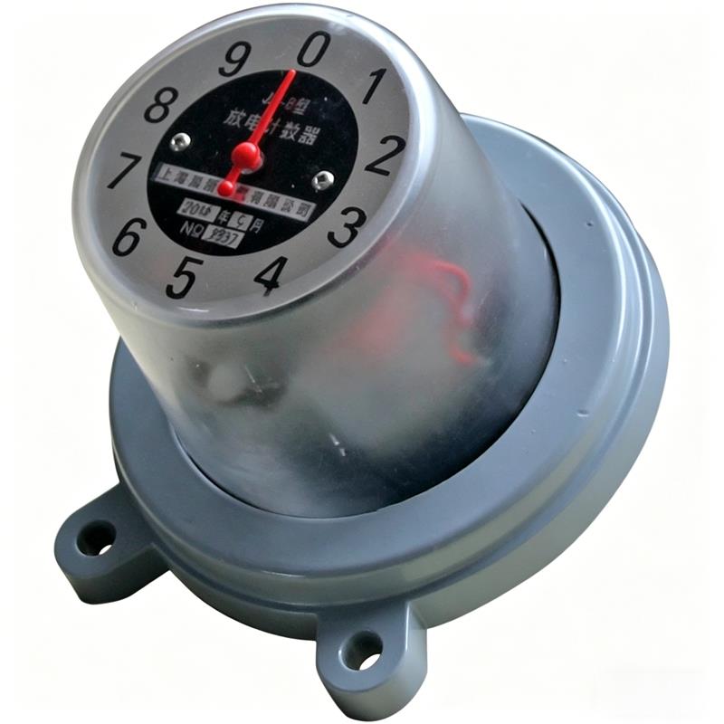
Product Details
1 Features
JS-8 discharge counter for arrester is an electrical device connected in series at the earthing terminal of the arrester for recording the number of arrester operations. It is suitable for metal oxide arresters (MOA) and valve-type arresters of 220kV and below voltage grades, effectively improving the operational reliability of arresters and the power supply quality of the system. The service environment of this discharge counter is the same as its matching arrester, making it a key monitoring device for power system overvoltage protection.
2 Structure and Performance
JS-8 Discharge Counter mainly consists of signal input circuit, discharge counting circuit and protection circuit, with compact and reliable structure. When the arrester operates, this counter can accurately accumulate and record the number of discharges, and automatically returns to zero after full scale, achieving cyclic counting for long-term monitoring by operation and maintenance personnel. The performance of JS-8 discharge counter fully complies with JB2440-91 "Discharge Counter for Arrester" industry standard, ensuring its stability and accuracy in harsh power environments.
Specifications and Main Performance of Discharge Counter
| No. | Main Performance | Product Model JS-8 |
|---|---|---|
| 1 | Applicable Power System Rated Voltage kV (RMS) | 35-220 |
| 2 | Nominal Discharge Current Level 8/20us kA (Peak) | 10 |
| 3 | Counting Current Range 8/20us A (Peak) | 50~100000 |
| 4 | Residual Voltage at Nominal Discharge Current kV (Peak) | 3.0 |
| 5 | 2ms Square Wave Impulse Current Withstand A (Peak) | 600×18 |
| 6 | 4/10us Current Impulse Withstand kA (Peak) | 100×2 |
| 7 | Weight kg | 3.0 |
3.1 Installation Diagram
3.2 Installation Method (see Figure 1)
3.2.1 First use Φ2.5mm wire L to firmly connect both ends (upper and lower flanges) of the arrester base D, connect the lower flange first then the upper flange, so that the arrester earthing terminal is reliably grounded, as shown in Figure 1(a):
3.2.2 Firmly install the discharge counter between the upper and lower flanges of the arrester base, as shown in Figure 1(b): First connect the discharge counter flange as grounding to the lower flange of the arrester base, then connect the high voltage outgoing terminal of the discharge counter to the upper flange of the arrester base.
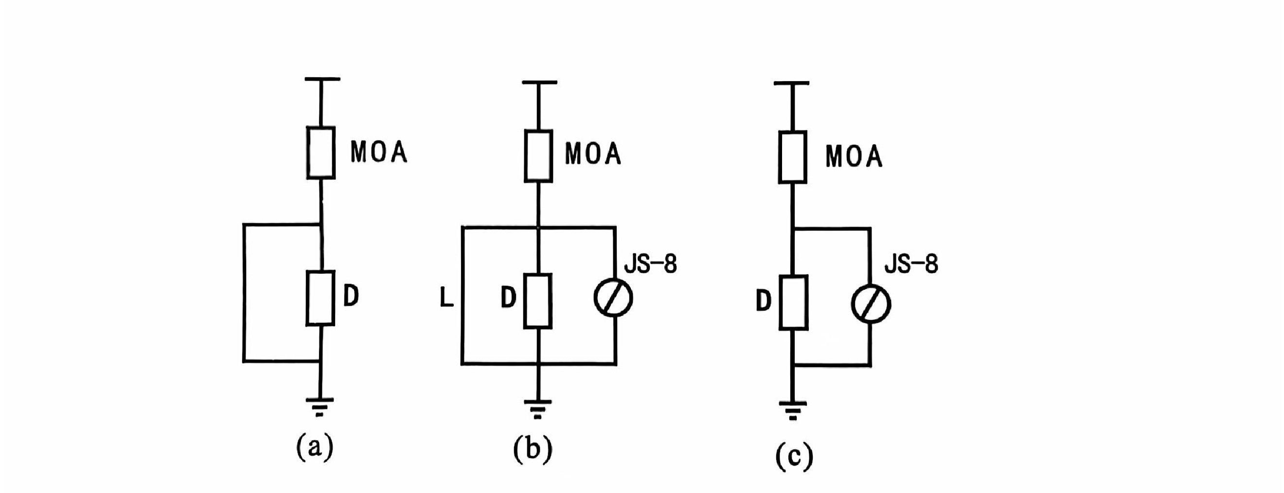
Figure 1 JS-8 Discharge Counter Installation Diagram
JS-8 Discharge Counter MOA: Arrester
D: Base L: Φ2.5mm Wire
3.2.3 Remove the wire L between both ends (upper and lower flanges) of the arrester base D, so that the discharge counter is connected in series between the arrester and ground, as shown in Figure 1(c):
3.2.4 During installation, the tension of the high voltage outgoing terminal lead of the discharge counter shall not exceed 100N;
3.2.5 When the discharge counter needs to be removed, repeat 3.2.1, then remove the discharge counter
4. Inspection Method
The discharge counter should be inspected before commissioning and after one or two years of operation. When using JS-8 Discharge Counter for inspection, prepare one 1000V megohmmeter and one 600V 10μF capacitor. First rotate the megohmmeter to charge the capacitor. After the charging stabilizes, disconnect the charging circuit while maintaining the megohmmeter speed, then discharge the charged capacitor to the high voltage outgoing terminal and earthing terminal of the discharge counter. The discharge counter should operate once. Test 10 times continuously, all should operate accurately, proving that the counting performance of the discharge counter is qualified.
5 User Instructions
5.1 If the discharge counter fails, please do not repair it yourself; it should be returned to the manufacturer for handling;
5.2 If the user uses this product in compliance with the instructions and it cannot be used due to quality issues within two years from the date of shipment, the company is responsible for the three guarantees;
5.3 Attached are the outline dimensions and installation drawing of JS-8 discharge counter.
6 Precautions
6.1 Do not apply 220V AC voltage across the discharge counter;
6.2 Do not apply steady-state signals when performing counting operation tests on the discharge counter.
Remarks:
If the counter pointer is not at zero, it is due to mechanical vibration during transportation. Counting can start from the actual number, which does not affect use and is normal.
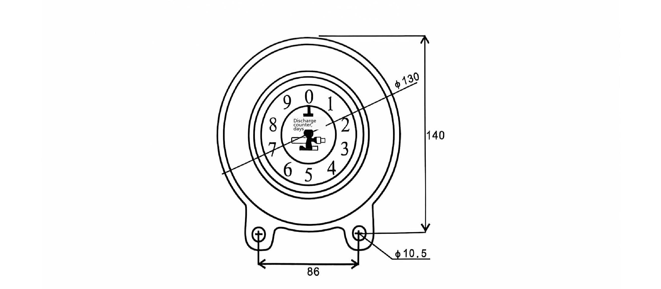
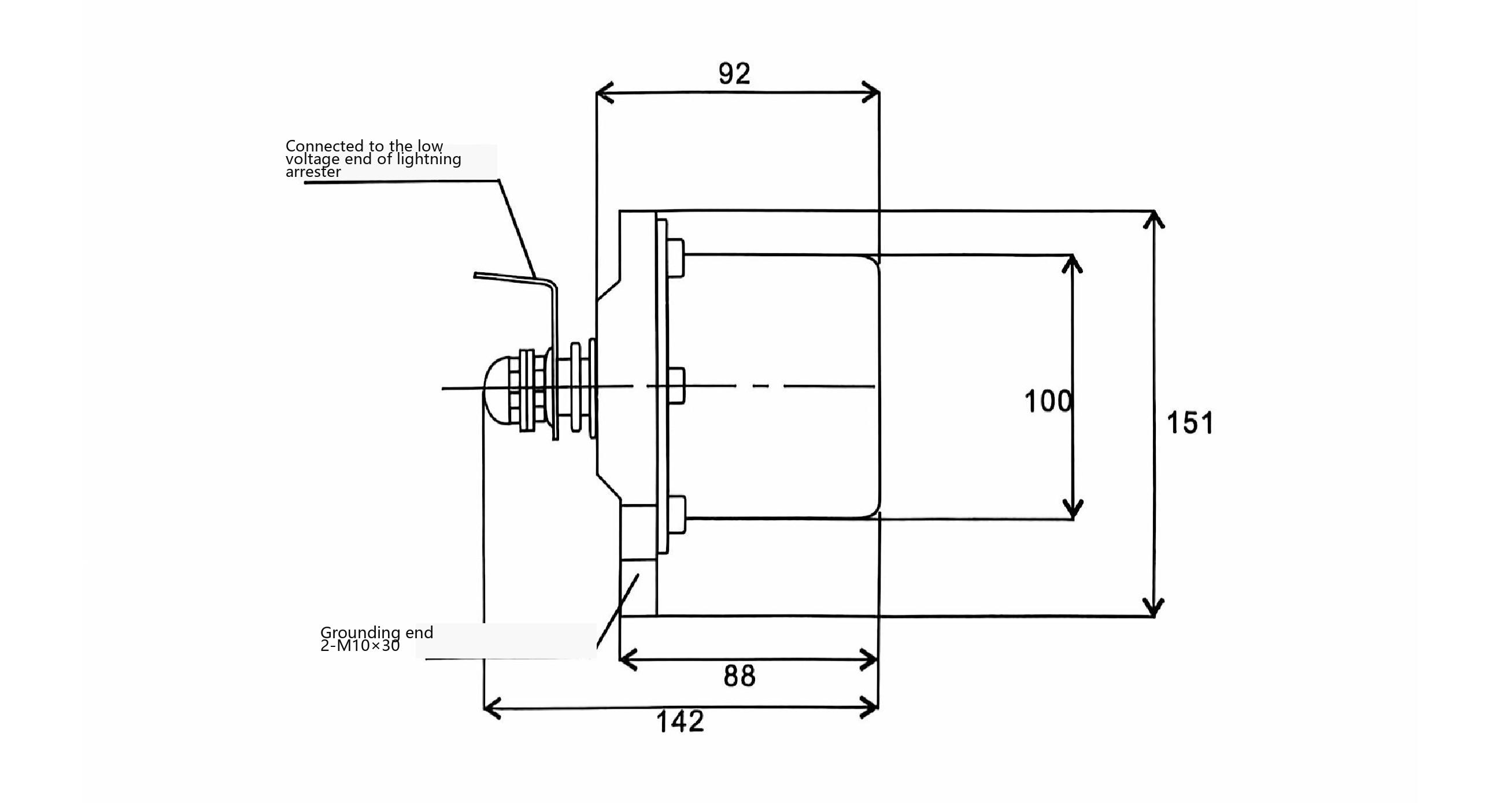
JS-8_Discharge Counter_Discharge Recording Device for Arrester

Telephone

Online Service

Follow Us


TikTok

Back to Top


