
Zinc Oxide Arrester
Product Title
Product Details
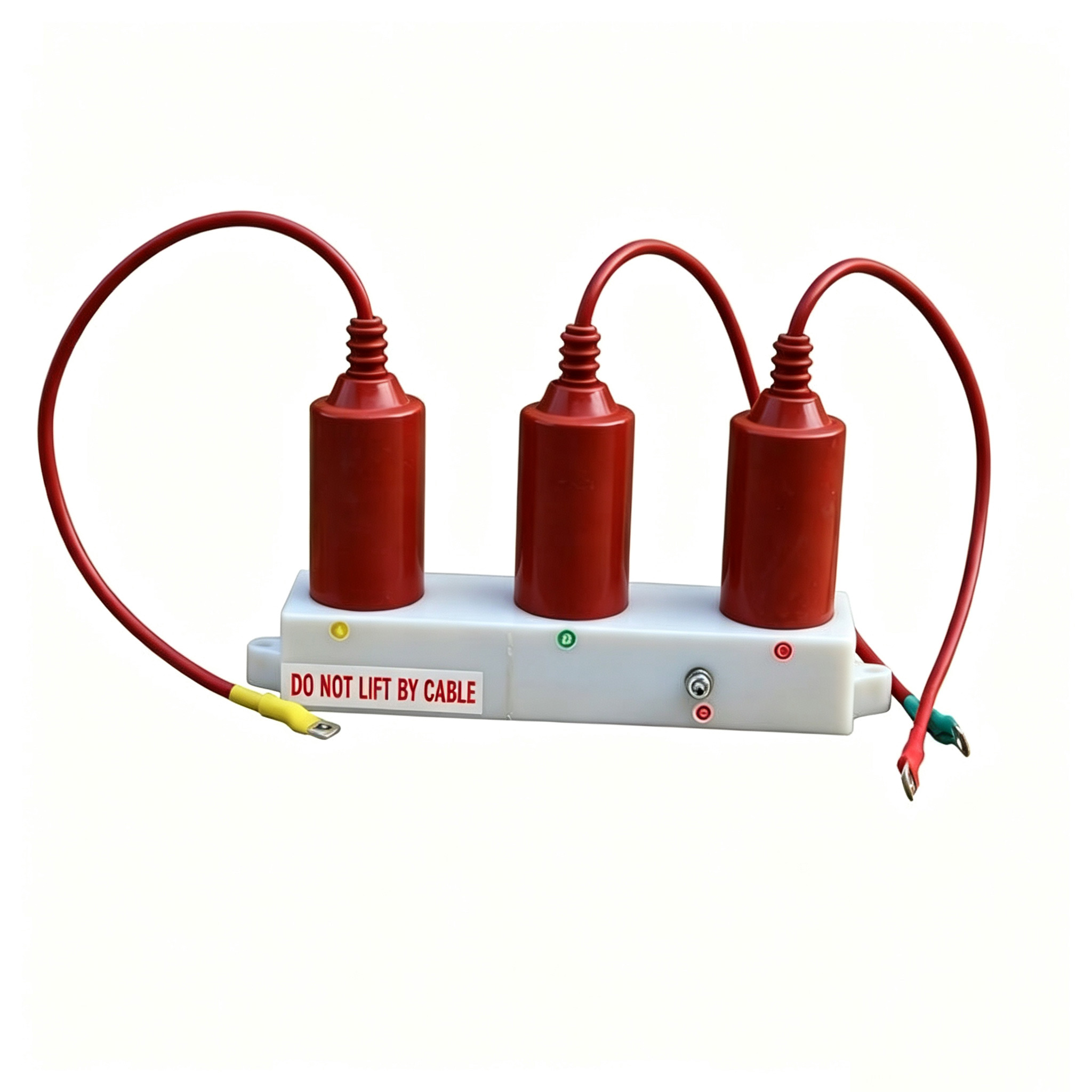
TBP series 10kV and below cabinet three-phase combination overvoltage protectors (three-phase combination arresters) are a new type of arrester used to protect the insulation of power equipment from overvoltage damage, with the characteristic of limiting phase-to-earth overvoltages while also effectively limiting inter-phase overvoltages, which ordinary arresters cannot achieve. The product is widely used for protecting vacuum switches, rotating motors, shunt compensation capacitors, power plants, substations and other locations. Three-phase combination overvoltage protectors have been in operation for many years, and practice has proven to be a practical and effective measure for limiting inter-phase overvoltages. One combination protector can serve the function of six ordinary arresters. Since the protector uses large-capacity zinc oxide resistor discs as the main component internally, it has good volt-ampere characteristics and overvoltage absorption capability, providing reliable protection for protected equipment, and is well received by the power system.
Due to some particularities of China's medium voltage power grids (3kV~66kV), conventional medium voltage arresters are not sensitive to such overvoltages and cannot provide protection. With the increasingly widespread use of vacuum switches, various operating voltages caused by their strong interrupting capability have raised new challenges for the protection of power equipment. Combination overvoltage protectors were developed precisely to solve this problem. This type of product adopts a four-star connection method (commonly known as the trident connection method), setting a common neutral point, which can greatly reduce inter-phase overvoltages while also substantially improving the phase-to-earth protection level, truly achieving effective limitation of vacuum switch operating overvoltages. FAURE Gaosuo Electric Co., Ltd. produces and sells products with composite insulation, compact structure, fully enclosed integral vulcanization molding. High-quality metal oxide valve plates and self-blowing special gaps are selected, with high operating characteristics, safety and convenience. It is particularly suitable for use with different models of medium voltage complete switchgear such as KYN, XGN, GBC, JYN, GZS, or can be directly installed in small compact substations.
TBP series 10kV and below cabinet three-phase combination arrester products comply with national standards GB11032-2000 "AC Gapless Metal Oxide Arresters", JB/T10496-2005 "AC Three-phase Combination Gapless Metal Oxide Arresters", ZBK49005-90 "Gapped Metal Oxide Arresters for AC Systems", JB/T8459-2006 "Arrester Product Model Designation Method".
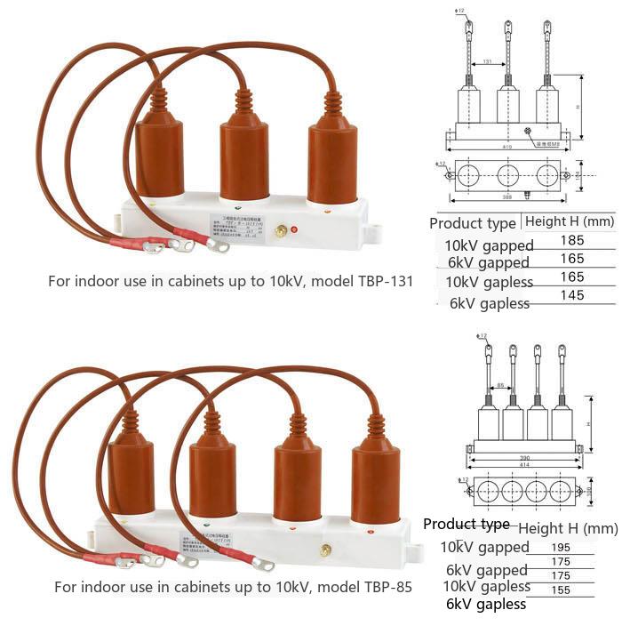
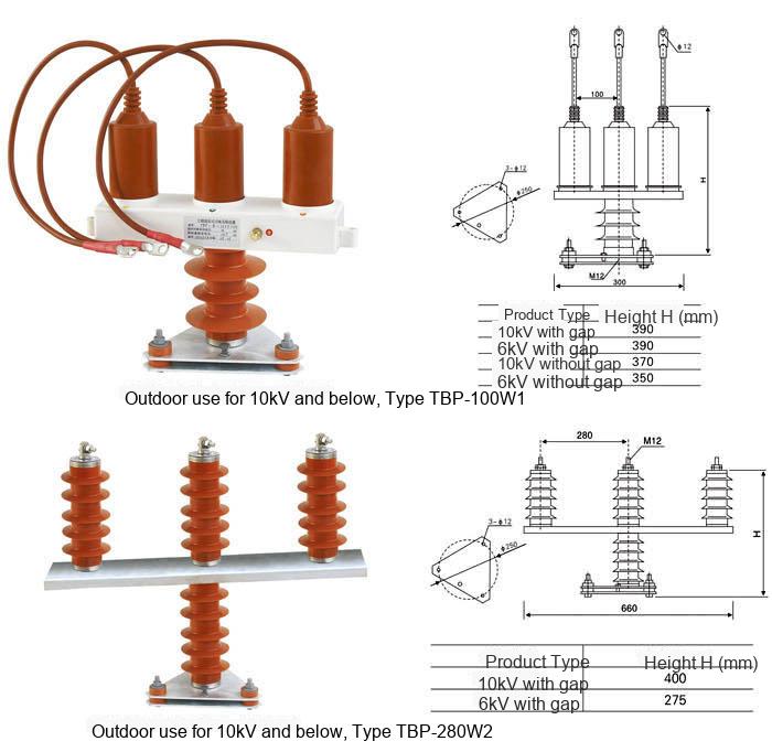
| Voltage level | Application place | Application environment | TBP protector standard model | No gap type | Gap type | Nominal residual voltage(kV) | ||||||||
| Rated voltage of protector (kV) RMS | Continuous operating voltage of protector (kV) | DC 1mA reference voltage (kV) (not less tdan) | Maximum leakage under 0.75 times DC 1mA voltage (μA) | Power frequency discharge voltage (kV) (not less tdan) | 1.2/50 impulse discharge voltage (kV) peak (not more tdan) | Maximum conducting current (μA) | 8/20 lightning impulse current peak (not more tdan) | 30/60 switching impulse current peak (not more tdan) | 2000μS square wave flow capacity (A) | 4/10 high current witdstand capability (kV) | ||||
| Phase to phase / Phase to ground (only one number means tde parameters of phase to phase and phase to ground are tde same) | ||||||||||||||
| 3KV | Type A for motor | Indoor | TBP-A-3.15/85 | 4 | 3.15 | 7.0/5.7 | 50 | - | - | - | 11.5/9.5 | 9.4/7.6 | 400 | 65 |
| TBP-A-3.15/131 | 4 | 3.15 | 7.0/5.7 | 50 | - | - | - | 11.8/9.5 | 9.4/7.6 | 400/200 | 65/40 | |||
| TBP-A-3.8F/85 | 3.8 | - | - | - | 7.5 | 9.5 | 20 | 9.5 | 7.6 | 400 | 65 | |||
| TBP-A-3.8F/131 | 3.8 | - | - | - | 7.5 | 9.5 | 20 | 9.5 | 7.6 | 400/200 | 65/40 | |||
| Outdoor | TBP-A-3.15/100W1 | 4 | 3.15 | 7.0/5.7 | 50 | - | - | - | 11.5/9.5 | 9.4/7.6 | 400 | 65 | ||
| TBP-A-3.15/280W2 | 4 | 3.15 | 7.0/5.7 | 50 | - | - | - | 11.8/9.5 | 9.4/7.6 | 400 | 65 | |||
| TBP-A-3.8F/100W1 | 3.8 | - | - | - | 7.5 | 9.5 | 20 | 9.5 | 7.6 | 400 | 65 | |||
| TBP-A-3.8F/280W2 | 3.8 | - | - | - | 7.5 | 9.5 | 20 | 9.5 | 7.6 | 400 | 65 | |||
| Type B for general substation use | Indoor | TBP-B-3/85 | 5 | 4 | 7.0/5.7 | 50 | - | - | - | 13.5 | 11.5 | 400 | 65 | |
| TBP-B-3/131 | 5 | 4 | 7.0/5.7 | 50 | - | - | - | 13.5 | 11.5 | 400/200 | 65/40 | |||
| TBP-B-3.8F/85 | 3.8 | - | - | - | 8 | 12 | 20 | 12 | 10.2 | 400 | 65 | |||
| TBP-B-3.8F/131 | 3.8 | - | - | - | 8 | 12 | 20 | 12 | 10.2 | 400/200 | 65/40 | |||
| Outdoor | TBP-B-3/100W1 | 5 | 4 | 7.0/5.7 | 50 | - | - | - | 13.5 | 11.5 | 400 | 65 | ||
| TBP-B-3/280W2 | 5 | 4 | 7.0/5.7 | 50 | - | - | - | 13.5 | 11.5 | 400 | 65 | |||
| TBP-B-3.8F/100W1 | 3.8 | - | - | - | 8 | 12 | 20 | 12 | 10.2 | 400 | 65 | |||
| TBP-B-3.8F/280W2 | 3.8 | - | - | - | 8 | 12 | 20 | 12 | 10.2 | 400 | 65 | |||
| 6KV | Type A, for motor | Indoor | TBP-A-6.3/85 | 8 | 6.3 | 14.0/11.2 | 50 | - | - | - | 23.0/18.7 | 18.7/15.0 | 400 | 65 |
| TBP-A-6.3/131 | 8 | 6.3 | 14.0/11.2 | 50 | - | - | - | 23.0/18.7 | 18.7/15.0 | 400/200 | 65/40 | |||
| TBP-A-7.6F/85 | 7.6 | - | - | - | 15 | 18.7 | 20 | 18.7 | 15 | 400 | 65 | |||
| TBP-A-7.6F/131 | 7.6 | - | - | - | 15 | 18.7 | 20 | 18.7 | 15 | 400/200 | 65/40 | |||
| Outdoor | TBP-A- 6.3/100W1 |
8 | 6.3 | 14.0/11.2 | 50 | - | - | - | 23.0/18.7 | 18.7/15.0 | 400 | 65 | ||
| TBP-A- 6.3/280W2 |
8 | 6.3 | 14.0/11.2 | 50 | - | - | - | 23.0/18.7 | 18.7/15.0 | 400 | 65 | |||
| TBP-A- 7.6F/100W1 |
7.6 | - | - | - | 15 | 18.7 | 20 | 18.7 | 15 | 400 | 65 | |||
| TBP-A- 7.6F/280W2 |
7.6 | - | - | - | 15 | 18.7 | 20 | 18.7 | 15 | 400 | 65 | |||
| Type B, universal for substation | Indoor | TBP-B-6/85 | 10 | 8 | 15.0/14.4 | 50 | - | - | - | 27 | 23 | 400 | 65 | |
| TBP-B-6/131 | 10 | 8 | 15.0/14.4 | 50 | - | - | - | 27 | 23 | 400/200 | 65/40 | |||
| TBP-B-7.6F/85 | 7.6 | - | - | - | 16 | 24 | 20 | 24 | 20.4 | 400 | 65 | |||
| TBP-B-7.6F/131 | 7.6 | - | - | - | 16 | 24 | 20 | 24 | 20.4 | 400/200 | 65/40 | |||
| Outdoor | TBP-B- 6/100W1 |
10 | 8 | 15.0/14.4 | 50 | - | - | - | 27 | 23 | 400 | 65 | ||
| TBP-B- 6/280W2 |
10 | 8 | 15.0/14.4 | 50 | - | - | - | 27 | 23 | 400 | 65 | |||
| TBP-B- 7.6F/100W1 |
7.6 | - | - | - | 16 | 24 | 20 | 24 | 20.4 | 400 | 65 | |||
| TBP-B- 7.6F/280W2 |
7.6 | - | - | - | 16 | 24 | 20 | 24 | 20.4 | 400 | 65 |
| 10kV | Type A for Motor | Indoor | TBP-A-10.5/85 | 13.5 | 10.5 | 23.2/18.6 | 50 | - | - | - | 38.0/31.0 | 31.0/25.0 | 400 | 65 |
| TBP-A-10.5/131 | 13.5 | - | 23.2/18.6 | 50 | - | - | - | 38.0/31.0 | 31.0/25.0 | 400/200 | 65/40 | |||
| TBP-A-12.7F/85 | 12.7 | - | - | - | 25 | 31 | 20 | 31 | 25 | 400 | 65 | |||
| TBP-A-12.7F/131 | 12.7 | 10.5 | - | - | 25 | 31 | 20 | 31 | 25 | 400/200 | 65/40 | |||
| Outdoor | TBP-A-10.5/100W1 | 13.5 | 10.5 | 23.2/18.6 | 50 | - | - | - | 38.0/31.0 | 31.0/25.0 | 400 | 65 | ||
| TBP-A-10.5/280W2 | 13.5 | - | 23.2/18.6 | 50 | - | - | - | 38.0/31.0 | 31.0/25.0 | 400 | 65 | |||
| TBP-A-12.7F/100W1 | 12.7 | - | - | - | 25 | 31 | 20 | 31 | 25 | 400 | 65 | |||
| TBP-A-12.7F/280W2 | 12.7 | 13.6 | - | - | 25 | 31 | 20 | 31 | 25 | 400 | 65 | |||
| Type B for Substation General | Indoor | TBP-B-10/85 | 17 | 13.6 | 25.0/24.0 | 50 | - | - | - | 45 | 38.3 | 400 | 65 | |
| TBP-B-10/131 | 17 | - | 25.0/24.0 | 50 | - | - | - | 45 | 38.3 | 400/200 | 65/40 | |||
| TBP-B-12.7F/85 | 12.7 | - | - | - | 26 | 41 | 20 | 41 | 35 | 400 | 65 | |||
| TBP-B-12.7F/131 | 12.7 | 13.6 | - | - | 26 | 41 | 20 | 41 | 35 | 400/200 | 65/40 | |||
| Outdoor | TBP-B-10/100W1 | 17 | 13.6 | 25.0/24.0 | 50 | - | - | - | 45 | 38.3 | 400 | 65 | ||
| TBP-B-10/280W2 | 17 | - | 25.0/24.0 | 50 | - | - | - | 45 | 38.3 | 400 | 65 | |||
| TBP-B-12.7F/100W1 | 12.7 | - | - | - | 26 | 41 | 20 | 41 | 35 | 400 | 65 | |||
| TBP-B-12.7F/280W2 | 12.7 | 13.6 | - | - | 26 | 41 | 20 | 41 | 35 | 400 | 65 | |||
| Type C for Capacitor | Indoor | TBP-C-10/85 | 17 | 13.6 | 25.0/24.0 | 50 | - | - | - | 46 | 35 | 400 | 65 | |
| TBP-C-10/131 | 17 | - | 25.0/24.0 | 50 | - | - | - | 46 | 35 | 400/200 | 65/40 | |||
| TBP-C-12.7F/85 | 12.7 | - | - | 50 | 26 | 41 | 20 | 41 | 33 | 400 | 65 | |||
| TBP-C-12.7F/131 | 12.7 | 13.6 | - | - | 26 | 41 | 20 | 41 | 33 | 400/200 | 65/40 | |||
| Outdoor | TBP-C-10/100W1 | 17 | 13.6 | 25.0/24.0 | - | - | - | - | 46 | 35 | 400 | 65 | ||
| TBP-C-10/280W2 | 17 | - | 25.0/24.0 | 50 | - | - | - | 46 | 35 | 400 | 65 | |||
| TBP-C-12.7F/100W1 | 12.7 | - | - | 50 | 26 | 41 | 20 | 41 | 33 | 400 | 65 | |||
| TBP-C-12.7F/280W2 | 12.7 | 7.69 | - | - | 26 | 41 | 20 | 41 | 33 | 400 | 65 | |||
| Type O for Neutral | Neutral | TBP-O7.6F | 10.5 | 40.8 | 11.4 | - | - | - | - | 19 | 15.9 | 400 | 65 |
| 35kV | Type B (General for Substation) | Indoor | TBP-B-35/200 | 51<,/TD> | 40.8 | 84/73 | 50 | - | - | - | 150/134 | 134/114 | 400 | 65 |
| TBP-B-35/310 | 51 | - | 84/73 | 50 | - | - | - | 150/134 | 134/114 | 400 | 65 | |||
| TBP-B-42F/200 | 42 | - | - | - | 80 | 124 | 20 | 124 | 105.4 | 400 | 65 | |||
| TBP-B-42F/310 | 42 | 40.8 | - | - | 80 | 124 | 20 | 124 | 105.4 | 400 | 65 | |||
| Outdoor | TBP-B-35/400W1 | 51 | 40.8 | 84/73 | 50 | - | - | - | 150/134 | 134/114 | 400 | 65 | ||
| TBP-B-35/630W2 | 51 | - | 84/73 | 50 | - | - | - | 150/134 | 134/114 | 400 | 65 | |||
| TBP-B-42F/400W1 | 42 | - | - | - | 80 | 124 | 20 | 124 | 105.4 | 400 | 65 | |||
| TBP-B-42F/630W2 | 42 | 40.8 | - | - | 80 | 124 | 20 | 124 | 105.4 | 400 | 65 | |||
| Type C (For Capacitor) | Indoor | TBP-C-35/200 | 51 | 40.8 | 84/73 | 50 | - | - | - | 150/134 | 122/105 | 400 | 65 | |
| TBP-C-35/310 | 51 | - | 84/73 | 50 | - | - | - | 150/134 | 122/105 | 400 | 65 | |||
| TBP-C-42F/200 | 42 | - | - | - | 80 | 124 | 20 | 124 | 100 | 400 | 65 | |||
| TBP-C-42F/310 | 42 | 40.8 | - | - | 80 | 124 | 20 | 124 | 100 | 400 | 65 | |||
| Outdoor | TBP-C-35/400W1 | 51 | 40.8 | 84/73 | 50 | - | - | - | 150/134 | 122/105 | 400 | 65 | ||
| TBP-C-35/630W2 | 51 | - | 84/73 | 50 | - | - | - | 150/134 | 122/105 | 400 | 65 | |||
| TBP-C-42F/400W1 | 42 | - | - | - | 80 | 124 | 20 | 124 | 100 | 400 | 65 | |||
| TBP-C-42F/630W2 | 42 | - | - | 80 | 124 | 20 | 124 | 100 | 400 | 65 |
| Parameter Name | Unit | Parameter Value |
|---|---|---|
| System Nominal Voltage | kV | 10 |
| Protector Model | - | TBP-B-12.7/131 |
| Continuous Operating Voltage | kV | 12.7 |
| DC 1mA Reference Voltage | kV | ≥24 |
| Nominal Discharge Current Residual Voltage (8/20μs) | kV | ≤131 |
| Switching Impulse Residual Voltage (30/60μs) | kV | ≤111 |
| Steep Wave Impulse Residual Voltage (1/5μs) | kV | ≤149 |
| Square Wave Current Capacity (2ms) | A | 400 |
| High Current Impulse Withstand (4/10μs) | kA | 65 |
| Applicable Cabinet Types | - | KYN, XGN, GBC, JYN, GZS, etc. |
This TBP-B-12.7/131 10kV overvoltage protector adopts a three-phase combination design, with high-quality zinc oxide resistor discs as the internal core, ensuring excellent nonlinear volt-ampere characteristics and fast absorption and limitation of overvoltage energy. Its four-star connection method can suppress both inter-phase and phase-to-earth overvoltages simultaneously, one unit can replace six ordinary arresters, providing comprehensive protection for vacuum switches, rotating motors and capacitor banks. The composite insulation fully enclosed structure makes it compact and easy to install, especially suitable for use in the limited space of various medium voltage switchgear, making it a reliable choice for improving the overvoltage protection level of 10kV distribution systems.
TBP-B-12.7/131_10kV Overvoltage Protector_Cabinet Three-phase Combination Arrester

Telephone

Online Service

Follow Us


TikTok

Back to Top


