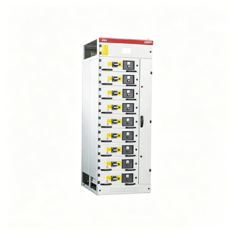
MNS Low-voltage Withdrawable Switchgear | Electrical Energy Conversion, Distribution and Control for AC 660V and Below Power Distribution Systems
Overview
This series of low-voltage withdrawable switchgear is a factory-built (FBA) modular combination cabinet type.
This series of low-voltage withdrawable switchgear is suitable for power plants, substations, petrochemical, metallurgical rolling, transportation energy, light industry and textile factories and mines, residential communities, high-rise buildings and other locations, for electrical energy conversion, distribution and control of power distribution equipment in power systems with AC 50~60Hz, rated working voltage up to 660V and below.
This device complies with GB 7251.1 "Low-voltage Switchgear and Controlgear Assemblies" and JB/T 9961 "Low-voltage Withdrawable Switchgear and Controlgear Assemblies" national standards and professional standards, and also complies with IEC 439-1 professional standards. MNS low-voltage withdrawable switchgear is assembled with standard profiles, with strong drawer unit interchangeability, and can flexibly combine feeder, motor control and reactive power compensation solutions, suitable for distribution systems in large industrial and mining enterprises.
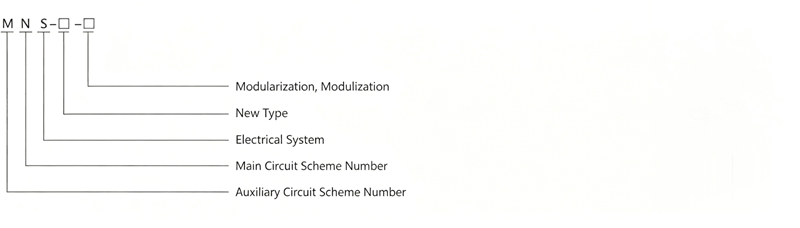
Model and Meaning
Normal Environmental Conditions for Use
- Ambient air temperature not higher than +40C, not lower than -5C, and the average temperature within 24h not higher than +35C.
- Atmospheric conditions: clean air, relative humidity not exceeding 50% at the upper limit temperature of +40C, with higher relative humidity allowed at lower temperatures, for example 90% at +20C, but considering that condensation may occasionally occur due to temperature changes.
- Altitude not exceeding 2000m.
- This device is suitable for transportation and storage in the temperature range of -25C to +55C, and for short periods (not exceeding 24h) up to +70C. At these temperatures, the device should not suffer any irreversible damage and should be able to operate normally under normal conditions.
- If the above conditions cannot be met, the user and manufacturer should negotiate a solution.
- If this device is used on offshore oil drilling platforms and nuclear power plants, a separate technical agreement should be signed.
Basic Technical Parameters
| Rated Performance |
Parameter |
| Rated Insulation Voltage | 660V(1000V) |
| Maximum Working Voltage of Main Busbar | 380V, 660V |
| Rated Withstand Current of Main Busbar | 5000A |
| Rated Short-time Withstand Current of Main Busbar | 100kA/1s |
| Maximum Working Current of Distribution Busbar (Vertical Busbar) | 1200A |
| Peak Current of Distribution Busbar (Vertical Busbar) Standard Type | 105kA (Max)/0.1s |
Peak Current of Distribution Busbar (Vertical Busbar) Enhanced Type | 176kA (Max)/0.1s |
Protection Levels
- Complies with IEC 529, DIN 40050 standards
- IP30 protection against solid objects larger than Φ2.5MM
- IP40 protection against solid objects larger than Φ1.0MM
- IP54 protection against dust and splashing water from any direction (consult manufacturer when ordering IP54 protection level)
Cabinet Structure
The basic cabinet structure of the switchgear is assembled from C-section profiles. The C-section is made of steel plate bent with mounting holes on a module of E=25mm. All frames and internal partitions are galvanized and phosphated. The doors and side panels are electrostatically sprayed with plastic. The basic cabinet structure is shown in Figure 1; basic cabinet dimensions are shown in Figure 2, Table 1, Table 2.
Switchgear Types
- Power Distribution Center (PC): Can use Emax, MT, 3WN, AH, ME series circuit breakers.
- Motor Control Center (MCC): Can use Emax, MT, 3WN, AH, ME series circuit breakers.
- Motor control center, automatic and remote power factor compensation assembly. The main switch for each circuit uses a high-breaking molded case circuit breaker or a rotary load switch with fuse. Automatic power factor compensation cabinet (with manual, automatic and remote power factor compensation devices).
A Power Distribution Center (PC) Cabinet
| Height H |
Width B |
Depth T |
T1 |
T2 |
Remark |
| 2200 | 400 | 1000 | 800 | 200 | Main busbar adapter F,s-1250-2000 ME630-1605 |
| 2200 | 600 | 1000 | 800 | 200 | F,s-2500 |
| 2200 | 800 | 1000 | 800 | 200 | F,s-3200 me2500-3200 |
| 2200 | 1000 | 1000 | 800 | 200 | F,s-4000 Me3205 |
| 2200 | 1200 | 1000 | 800 | 200 | ME4005 |
B Motor Control Center (MCC) Cabinet
| Height H |
Width B |
B1 |
B2 |
Depth T |
T1 |
T2 |
Remark |
| 2200 | 1000 | 600 | 400 | 600 | 400 | 200 | Single-sided operation |
| 2200 | 1000 | 600 | 400 | 1000 | 400 | 200 | Double-sided operation |
C-Section Profile Frame Structure (Figure 1)
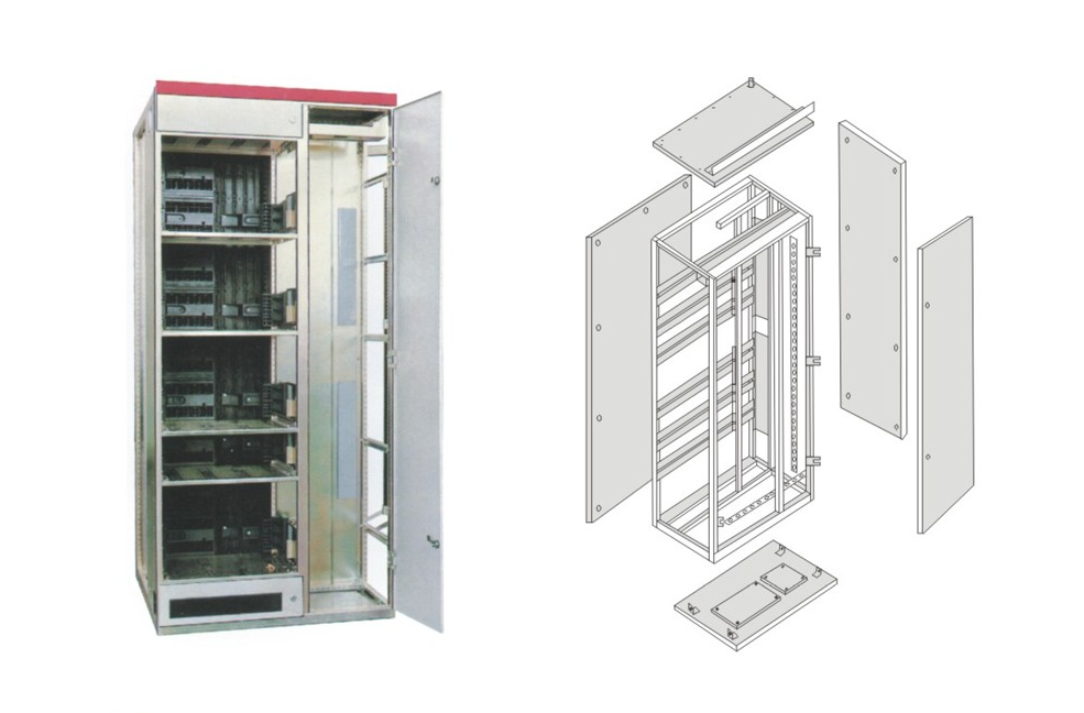
Cabinet Schematic Diagram (Figure 2)
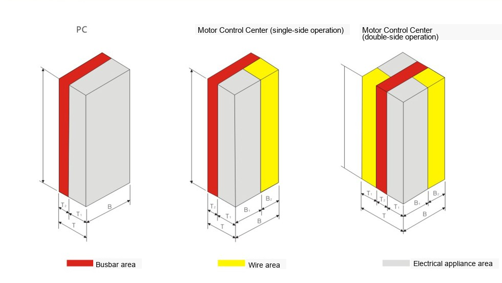
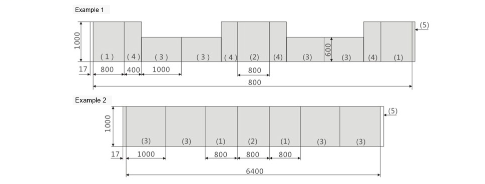
Combination Method Diagram (Figure 3)
Installation, Operation, Maintenance
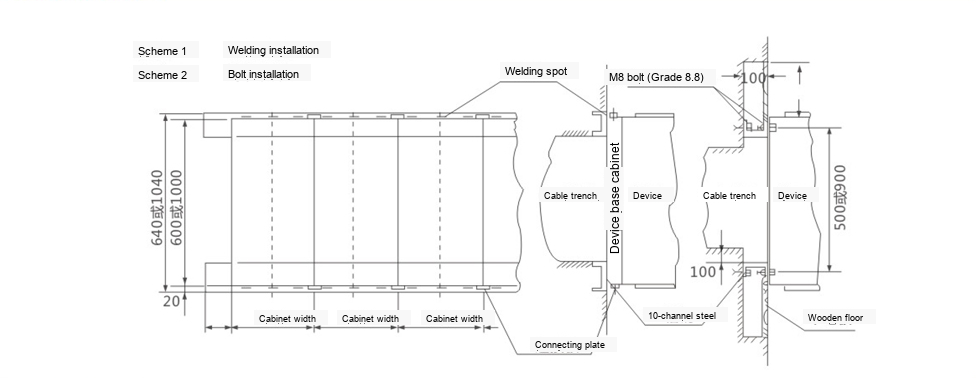
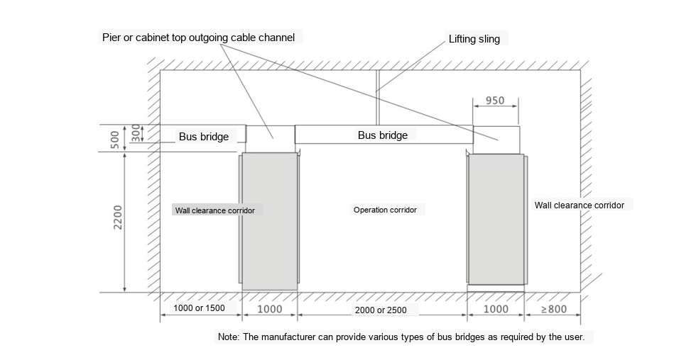
- Refer to Figures 4 and 5 for installation.
- Upon arrival, first check whether the packaging is intact. If the device is not to be installed immediately, store it in a dry, clean place.
- The device is recommended for floor-standing installation, but can also be installed in other positions. The installation foundation and platform surface should be level, with an inclination of less than 1deg and a total length deviation of ≤3mm.
- Bolted connections of all conductive parts should use M8 grade bolts and spring washers. Recommended tightening torques are shown in the table below:
| Bolt Specification | Recommended Tightening Torque (N·m) |
| M6 | 9.5 |
| M8 | 25 |
| M10 | 45 |
| M12 | 80 |
| M16 | 200 |
- After installation and adjustment, before commissioning, the following inspections and tests should be carried out:
- 1. Check the appearance and interior of the cabinet, electrical equipment and devices, and wiring to ensure they meet the product drawing requirements.
- 2. Check that the manual operating mechanisms and electrical protection devices operate normally and reliably.
- 3. Check that the mechanical interlocking and control, and electrical interlocking operate in accordance with design requirements.
- 4. Check that the insulation resistance of the main circuit and control circuit meets specified requirements.
- 5. Check that the contacts of electrical equipment installed in the device are in good condition and meet the technical requirements of the equipment itself.
- 6. Check whether there are any foreign objects inside the device and whether the mounting screws of various components are loose.
- Precautions for operating withdrawable MCC cabinets.
Transportation and Storage of the Device
- The device must not be tilted or subjected to severe vibration.
- When lifting after unpacking, use wire ropes with an angle between the two ropes of <120deg.
- When lifting after unpacking, use a transport pallet and do not lift from the four corners of the test.
- Prevent rain and moisture. Ambient temperature should be in accordance with the product sample specifications.
Completeness of the Product
The switchgear is supplied with a packing list, product certificate, product instruction manual, necessary drawings, door keys for the supplied accessories, and spare parts according to the supporting list.
Installation Diagram (Figure 4)
Busbar Bridge Installation Diagram (Figure 5)
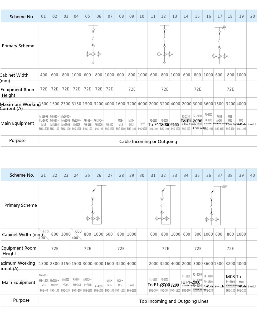
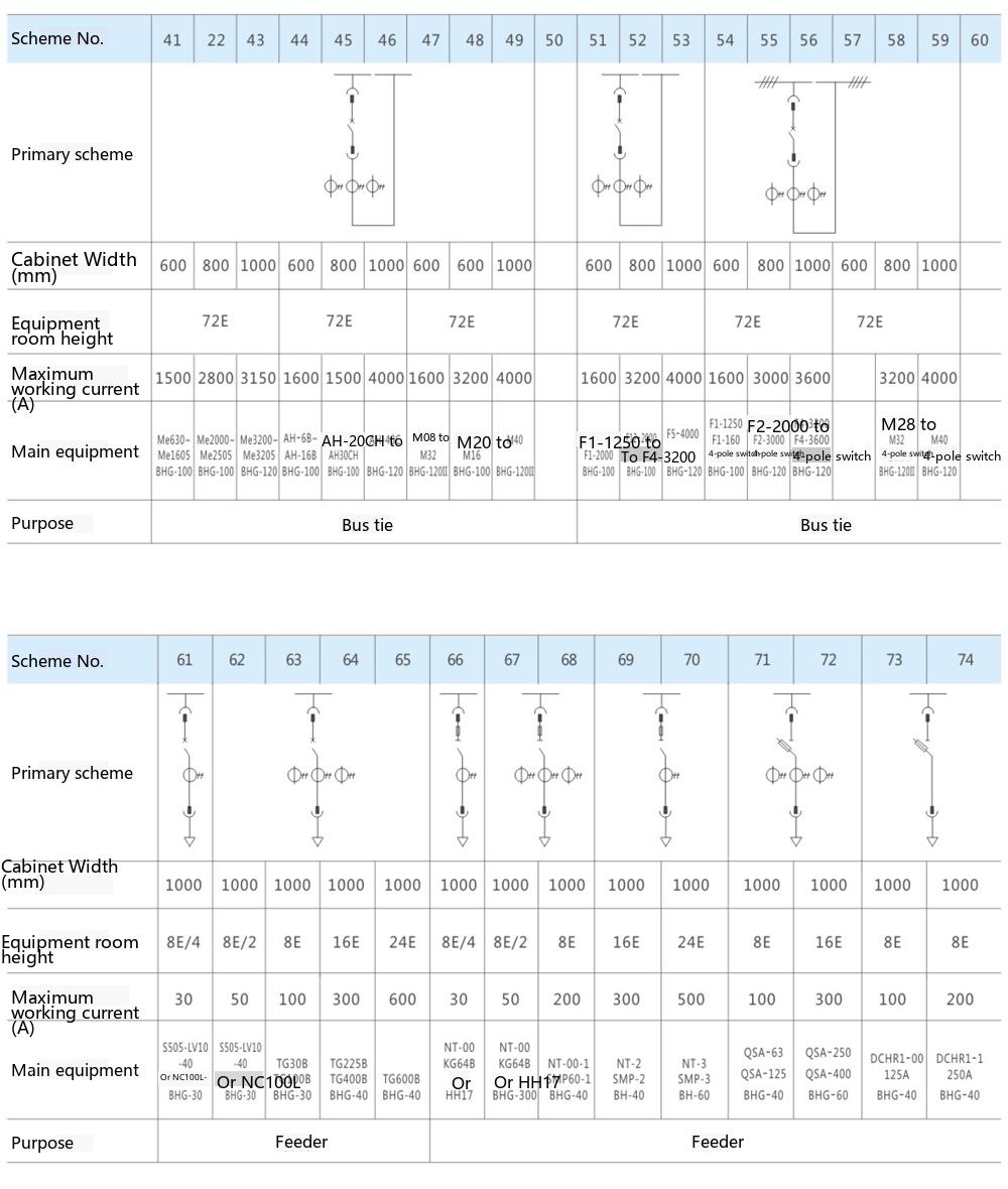
Single-Line Main Circuit Schemes
MNS Low-voltage Withdrawable Switchgear | Electrical Energy Conversion, Distribution and Control for AC 660V and Below Power Distribution Systems