GCS Low-voltage Withdrawable Switchgear Withdrawable Power Distribution Complete Device
Overview
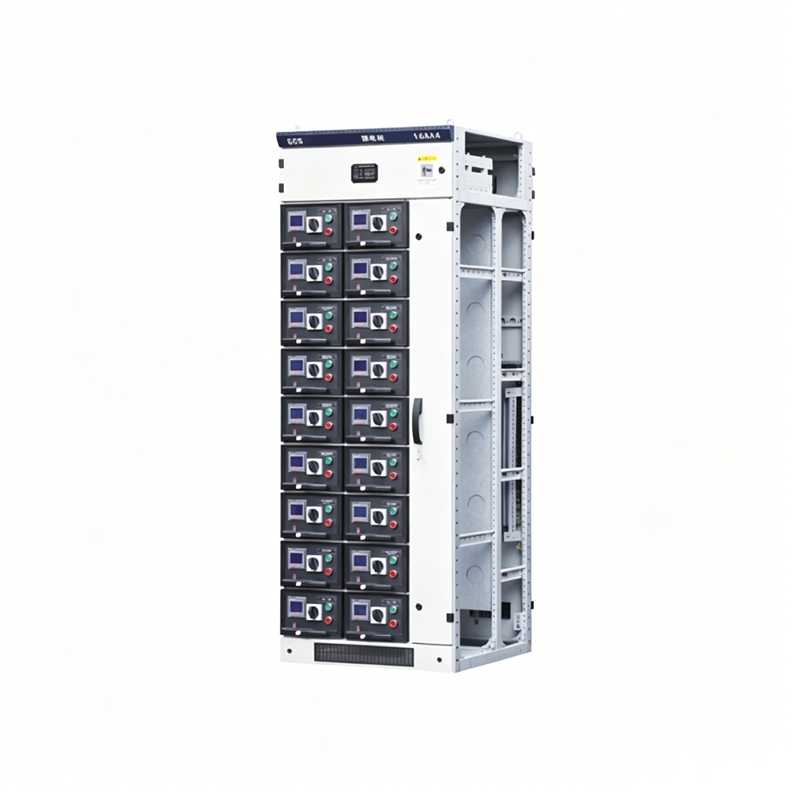
GCS low-voltage withdrawable switchgear is suitable for power distribution systems in power plants, petroleum, chemical, metallurgy, textile, high-rise buildings and other industries. In large power plants, petrochemical systems and other places with high automation requirements and the need for computer interfaces, it serves as a low-voltage complete distribution device for power distribution, centralized motor control, and reactive power compensation in power generation and supply systems with three-phase AC frequency of 50(60)Hz, rated working voltage of 380V(400V), (660V), and rated current of 4000A and below.
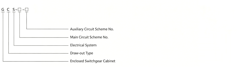
Model and Meaning
Performance Indicators
The design of the device complies with the following standards: IEC 439 - Low-voltage Switchgear and Controlgear Assemblies, GB 72501 Low-voltage Switchgear and Controlgear Assemblies, ZBK 36001 Low-voltage Withdrawable Switchgear and Controlgear Assemblies. The GCS low-voltage withdrawable switchgear meets the requirements of the above standards in all performance indicators.
Basic Technical Parameters
| Item | Parameter |
|---|
| Main Circuit Rated Voltage (V) | AC 380(400), (660) |
| Auxiliary Circuit Rated Voltage (V) | AC 220, 380(400) DC 110, 220 |
| Rated Frequency (Hz) | 50(60) |
| Rated Insulation Voltage (V) | 660(1000) |
| Rated Current (A) | Horizontal Busbar | ≤4000 |
| Vertical Busbar (MCC) | 1000 |
| Busbar Rated Short-time Withstand Current (kA, 1s) | 50, 80 |
| Busbar Rated Peak Withstand Current (kA/0.1s) | 105, 176 |
| Power Frequency Test Voltage (V/1 min) | Main Circuit | 2500 |
| Auxiliary Circuit | 1760 |
| Three-phase Four-wire Busbar | A.B.C.PE.N |
| Three-phase Five-wire Busbar | A.B.C.PE.N |
| Protection Level | IP30, IP40 |
Main Structure
- The main frame uses 8MF open-section steel, with mounting holes of 20mm, 100mm and φ9.2mm modules on the two sides of the steel, allowing flexible internal installation.
- The main frame assembly is designed in two types: fully assembled structure and partially welded structure (side frame and cross beams), for user selection.
- The functional compartments of the device are isolated from each other, divided into functional unit compartment, busbar compartment and cable compartment. The functions of each compartment are relatively independent.
- The horizontal busbar is arranged horizontally at the rear of the cabinet to enhance the busbar's ability to withstand electrodynamic forces, serving as a basic measure to give the main circuit high short-circuit strength capability.
- The design of the cable compartment facilitates convenient cable entry and exit from both top and bottom.
The standard cabinet height of the device is fixed at 2200mm, with width and depth dimensions as shown in the table below:
| Width (mm) | Depth (mm) | Height (mm) |
|---|
| 400 | 800, 1000 | 2200 |
| 600 | 800, 1000 | 2200 |
| 800 | 600, 800, 1000 | 2200 |
| 1000 | 600, 800, 1000 | 2200 |
Functional Units
- The drawer height module is 160mm, divided into five size series: 1/2 unit, 1 unit, 3/2 unit, 2 unit, 3 unit. The rated current of the unit circuit is 400A and below.
- Drawer changes only in height dimension, with width and depth dimensions unchanged. Drawers of the same functional unit have good interchangeability.
- Each MCC cabinet can accommodate up to 11 one-unit drawers or 22 1/2-unit drawers. Drawers above one unit use multi-functional rear plates.
- Drawer incoming and outgoing connections use plug-in units of the same specification with different numbers of pieces according to current size.
- The connection between 1/2-unit drawers and the cable compartment uses a backplane-type ZJ-2 adapter.
- The connection between unit drawers and the cable compartment uses ZJ-1 adapters with rod or tube structure of the same dimensions, divided by current rating.
- Drawer units are equipped with mechanical interlocking devices.
Main Electrical Components
- The selection principle for main electrical components is based on imported technology that can be mass-produced domestically in series while meeting the device's high-performance requirements.
- The main circuit breaker for power supply and feeder units is the AH series, with other options including the M series from Schneider and the F series. The AH circuit breaker features good performance, compact structure, light weight, and strong serialization. It has a relatively low price, convenient maintenance and use, and its performance indicators meet the requirements of this device.
- The main circuit breakers for drawer units (motor control units, some feeder units) are the CM1 and TM30 series molded case circuit breakers, with some using the NZM100A series from MOELLER. These switches all feature good performance, compact structure, short or no arc, and high technical and economic indicators, meeting the requirements of this device.
- Disconnectors and fuse-disconnectors are selected from the Q series. This series has high reliability, strong breaking capacity, and可以实现 mechanical interlocking.
- The main fuses are selected from the NT series.
- AC contactors are selected from the B series and LC1-D series.
Device Features
- Increases the thermal capacity of adapters, significantly reducing the additional temperature rise caused by adapter temperature rise to plugs, cable terminals, and partition plates.
- Clear and reliable separation between functional units and compartments ensures that a fault in one unit does not affect the operation of other units, limiting faults to the smallest possible范围.
- The horizontal arrangement of busbars ensures good dynamic and thermal stability of the device, capable of withstanding short-circuit current impacts of 80/176kA.
- Each MCC cabinet can accommodate up to 22 circuits, fully considering the needs of automated motor groups in industries such as large single-unit capacity power generation and petrochemical systems.
- The connection between the device and external cables is completed in the cable compartment, with cables able to enter and exit from top or bottom. Current transformers are installed in the cable compartment for convenient installation and maintenance.
- In the same power distribution system, short-circuit current can be limited through current-limiting reactors to stabilize busbar voltage, partially reducing the short-circuit strength requirements for components.
- Drawer units have a sufficient number of secondary plug-in contacts (32 pairs for 1 unit and above, 20 pairs for 1/2 unit) to meet the contact quantity requirements of computer interfaces and automatic control circuits.
Auxiliary Circuits
The auxiliary circuit diagrams are designed in accordance with relevant design technical regulations such as the "Technical Regulations for Auxiliary Power Design of Thermal Power Plants", and are suitable for low-voltage auxiliary power systems in power plants and substations, as well as low-voltage distribution systems in industrial and mining enterprises and high-rise buildings.
Auxiliary circuit schemes are designed according to the functional units of main circuit schemes, including power incoming, feeder (PC), and motor feeder (MCC) operation control.
Installation and Operation
Upon arrival at the receiving location, first check whether the packaging is intact. If any problems are found, promptly notify the relevant contract department to make commercial records, jointly analyze the causes, and handle visa and aftermath matters. For products not to be installed immediately, they should be properly stored in a suitable place according to normal operating conditions and temporary storage regulations for electrical equipment.
Product installation should be carried out according to the installation diagram (see attached figures). The foundation channel steel and bolts for bolt fixing are to be provided by the user. When connecting the main busbar, if the surface is uneven due to transportation or storage, it should be leveled before connection and tightening.
When the device is installed singly or in a row, its verticality, cabinet surface unevenness, and cabinet gap deviations should comply with the following table.
| Item No. | Item | Tolerance (mm) |
|---|
| 1 | Verticality | 3.3 |
| 2 | Horizontal level of tops of two adjacent cabinets | 2 |
| Top of entire row of cabinets | 5 |
| 3 | Unevenness of two adjacent sides | 1 |
| Side of entire row of cabinets | 5 |
| 4 | Gap between cabinets | 2 |
Inspection and Testing Before Commissioning After Product Installation
- Check whether the cabinet surface paint or other covering materials (such as spray coating) are damaged, and whether the cabinet interior is dry and clean.
- Check whether the operating mechanisms of electrical components are flexible, without jamming or excessive operating force.
- Check whether the making and breaking of the main and auxiliary contacts of main electrical apparatus are reliable and accurate.
- Drawers or withdrawable mechanisms should slide flexibly and smoothly without jamming or collision.
- The centerlines of the moving and fixed contacts of the drawer or withdrawable structure should align, and the contact should be tight. The insertion depth of main and auxiliary contacts should meet requirements. Mechanical or electrical interlocking devices should operate correctly, and locking and unlocking should be reliable.
- Drawers of the same dimensions should be easily interchangeable without jamming or collision.
- The grounding contacts between the drawer and the cabinet should be in close contact. When the drawer is pushed in, the grounding contact should make contact before the main contact, and when pulled out, the grounding contact should disconnect after the main contact.
- The scale settings of instruments, transformer ratios, and polarities should be correct.
- The specifications of fuse links should comply with engineering design requirements.
- Protection ratings and settings should be correct and动作 reliable.
- Insulation resistance measured with a 1000V megohmmeter should not be less than 1MΩ.
- Busbar connections should be good, and insulating supports, mounting parts, and other accessories should be installed securely and reliably.
Figure 1, Installation Diagram
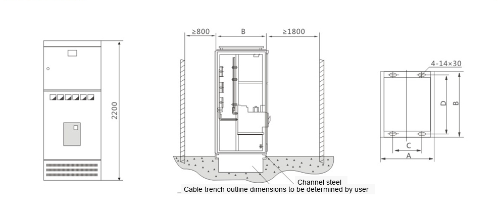
| General Cabinet Code | A | B | C | D | Remark |
|---|
| GCS-TG10-4 | 1000 | 1000 | 650 | 956 | Bus Coupler Cabinet |
| GCS-TG0810-4 | 800 | 1000 | 650 | 956 | Incoming Cabinet |
| GCS-TG0808-4 | 800 | 800 | 650 | 756 | Incoming Cabinet |
| GCS-TG088-4 | 800 | 800 | 650 | 756 | Incoming Cabinet |
Figure 2, PC Cabinet Installation Diagram
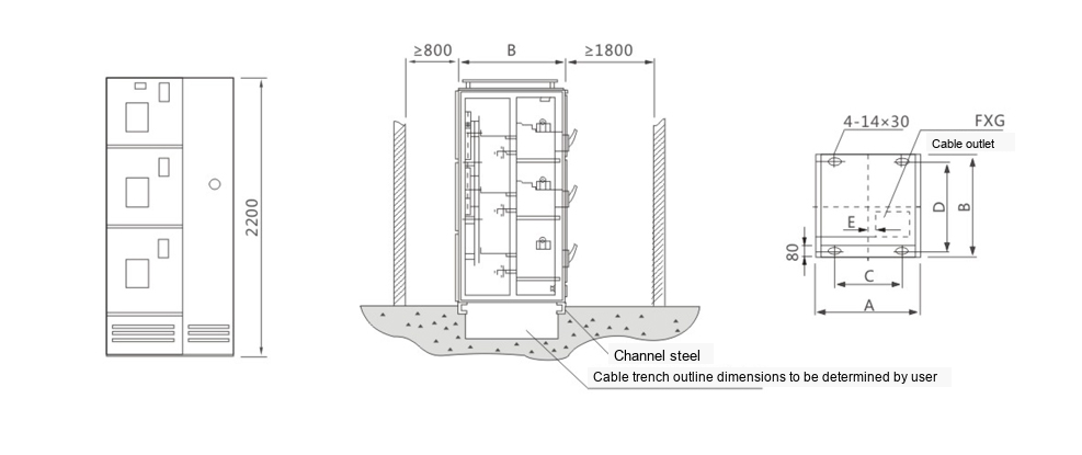
| General Cabinet Code | A | B | C | D | E | F×G |
|---|
| GCS-TG1010-2 | 1000 | 1000 | 650 | 956 | 160 | 400×400 |
| GCS-TG0810-2 | 800 | 1000 | 650 | 956 | 160 | 200×400 |
| GCS-TG0808-2 | 800 | 800 | 650 | 756 | 160 | 400×400 |
Figure 3, MCC Cabinet Installation Diagram
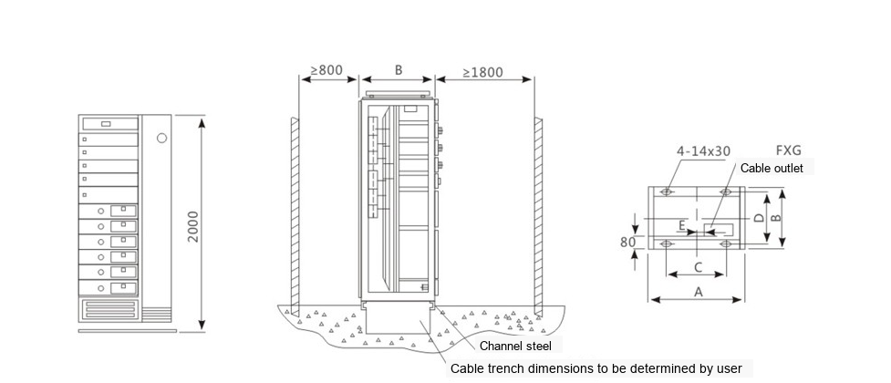
| General Cabinet Code | A | B | C | D | E | FXG |
|---|
| GCS-TG1006-1 | 1000 | 600 | 650 | 556 | 160 | 400×350 |
| GCS-TG0806-1 | 800 | 600 | 650 | 556 | 160 | 200×350 |
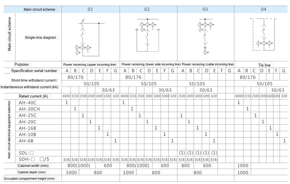
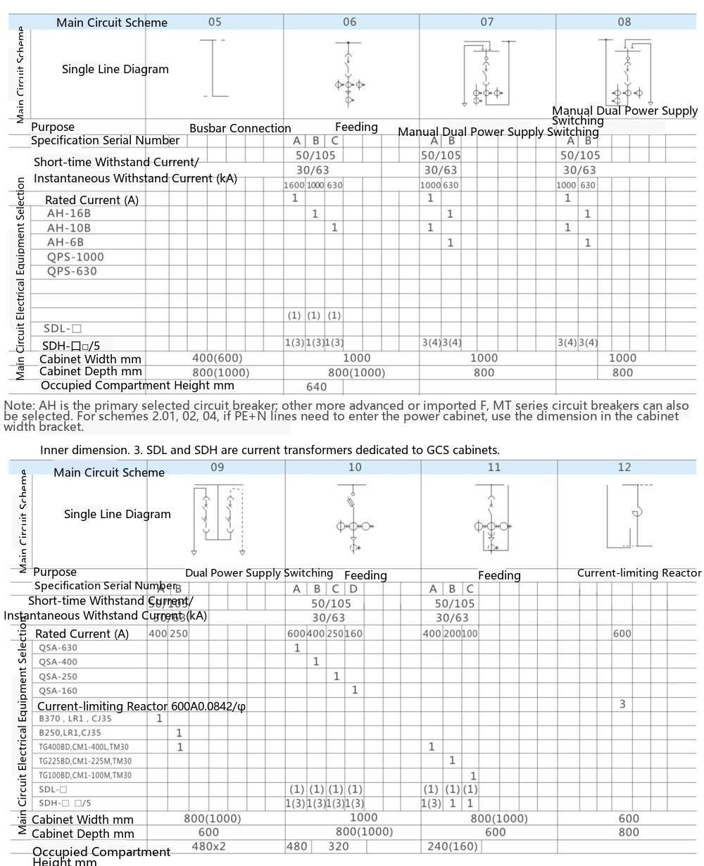
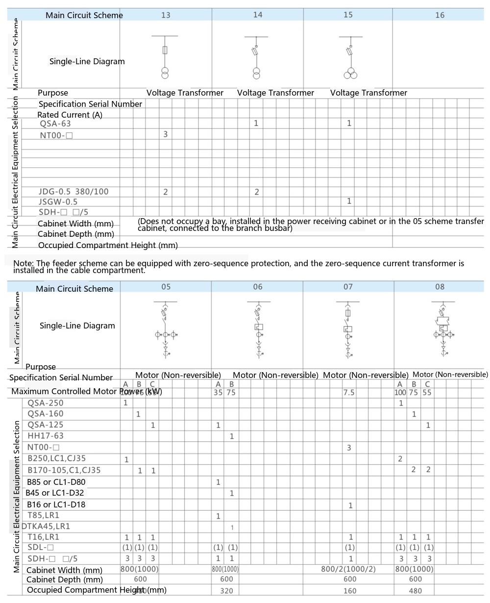
Single-Line Wiring Diagrams