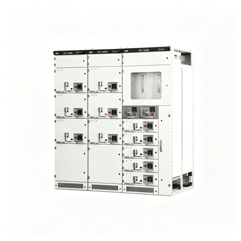
GCK Low-voltage Withdrawable Switchgear | Low-voltage Complete Distribution Equipment Power Distribution and Motor Control Center
Application
GCK low-voltage withdrawable switchgear consists of two parts: Power Distribution Center (PC) cabinets and Motor Control Center (MCC) cabinets. It is suitable for power users such as power plants, substations, industrial and mining enterprises as power distribution, motor control, and lighting distribution equipment in AC 50Hz, maximum working voltage up to 660V, maximum working current up to 3150A distribution systems for electrical energy conversion, distribution, and control. GCK low-voltage withdrawable switchgear adopts a drawer unit modular design, with each circuit independently separated without interference. The withdrawable operation facilitates maintenance and replacement, making it suitable for power distribution and motor control centers.
Features
This series of products has the advantages of high breaking capacity, good dynamic and thermal stability, reasonable structure, practical electrical schemes, strong serialization and versatility, arbitrary combination of various scheme units, more circuits accommodated in a single cabinet, saving floor space, beautiful appearance, high protection level, safety, reliability, and convenient maintenance.
This product complies with IEC 439 NEMA ICS 2-322 standards, also meets GB 7251-2005 "Low-voltage Switchgear and Controlgear Assemblies" national standard and ZBK 36001 "Low-voltage Withdrawable Switchgear and Controlgear Assemblies" professional standard.
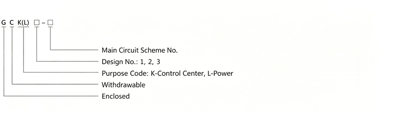
Model and Meaning
Environmental Conditions for Use
- Altitude not exceeding 2000m.
- Ambient air temperature not higher than +40C, and the average temperature within 24h not higher than +35C, ambient air temperature not lower than -5C.
- Atmospheric conditions: clean air, relative humidity not exceeding 50% at a temperature of +40C, with higher relative humidity allowed at lower temperatures, for example: 90% at +20C.
- Installation site free from fire, explosion hazards, heavy pollution, chemical corrosion and severe vibration.
- Inclination from the vertical not exceeding 5deg.
- This product is suitable for transportation and storage at the following temperatures: -25C~+55C, and for short periods (not exceeding 24h) not exceeding +70C.
- If the above conditions cannot be met, the user should raise the issue with our company when ordering for negotiation.
Main Technical Parameters of Switchgear
| Item |
Parameter |
| Rated Working Frequency (Hz) | 50 |
| Rated Working Voltage (V) | 380, 660 |
| Rated Insulation Voltage (V) | 660 |
| Rated Working Current (A) | Horizontal Busbar: 630-3150 |
| Vertical Busbar: 600 |
| Rated Short-time Withstand Current | Horizontal Busbar: 80kA (RMS) / 1 second |
| Vertical Busbar: 50kA (RMS) / 1 second |
| Rated Peak Withstand Current | Horizontal Busbar: 176kA/0.1s |
| Vertical Busbar: 110kA/0.1s |
| Main Circuit Plug-in (A) | 200, 400 |
| Auxiliary Circuit Plug-in (A) | 10 |
| Power Frequency Withstand Voltage 1 minute (V) | 2500 |
| Protection Level | IP40 |
| Operation Level | Local, Remote, Automatic |
Structural Features
The basic frame of this series of products is of combined assembled structure. All structural parts of the frame are connected by screws to form the basic frame, and then assembled into a complete switchgear with doors, baffles, partitions, drawers, mounting brackets, busbars and electrical components as needed. This cabinet has the following features:
- The frame uses steel section material, positioned with triangular plates, and bolted connections without welding, thus avoiding welding deformation and stress, improving installation accuracy.
- Mounting holes for the frame and components are based on module E=20mm.
- Internal structural parts are galvanized, and the exterior is pickled and phosphated, then coated with electrostatic epoxy powder.
- In the Power Distribution Center (PC) incoming cabinet, the top is the horizontal busbar area, and below the horizontal busbar area is the circuit breaker compartment. The circuit breaker can be equipped with domestic DW15C, ME series, or various circuit breakers from foreign electrical companies according to user needs, such as the F series circuit breakers and intelligent circuit breakers produced by ABB. Generally, PC units with a main circuit including a bus coupler (including bus coupler) with a rated current of 630A-1600A occupy one cabinet with external dimensions of 800×1000×2200 (W×D×H). Main circuits without a bus coupler occupy one cabinet with external dimensions of 800×800×2000 (W×D×H). For rated currents of 1600A-3150A, they occupy one cabinet with external dimensions of 1000×1000×2200 (W×D×H). Main circuits without a bus coupler occupy one cabinet with external dimensions of 1000×800×2200 (W×D×H). The Power Distribution Center (PC) feeder cabinet structure is similar to the incoming cabinet. For feeder currents of 630A-1600A, one 1000×1000×2200 (W×D×H) cabinet can accommodate two circuits, arranged one above the other.
- Motor Control Center (MCC) switchgear is available in wall-mounted and non-wall-mounted types. The top is the horizontal busbar area. Below the horizontal busbar area is the drawer functional unit area, with a width of 600mm and a height of 1840mm for the drawer functional unit area. When the cabinet is wall-mounted, the left part is the functional unit area, and the right part has a 200mm wide cable outgoing area. The external dimensions are 800/500/2200 (W, D, H). When the cabinet is free-standing, the width is 600mm, and the cable outgoing area is at the rear of the cabinet. The external dimensions are 600×800(1000)×2200 (W×D×H). The cabinet depth is available in 800 and 1000mm, with 1000mm recommended for uniformity with PC cabinets. When the drawer is pulled out of the cabinet, live parts inside the cabinet are not exposed, ensuring safety and reliability.
- The drawer functional unit and the door are mechanically interlocked by the operating mechanism of the main switch. When the main switch is in the closed position, the door cannot be opened, and the operating mechanism can be locked in the closed or open position with an external padlock. The functional unit compartments are separated by metal plates. Drawers have good interchangeability and have working, test, and disconnected positions. When the drawer is pushed to a certain position, it automatically latches. The latch can be released by pulling the plate on the left side of the drawer to move to the next position. The drawer also has an anti-drop function when pulled out of the cabinet.
- Fixed-type cabinets for capacitor compensation, metering, etc., have the same appearance and the same horizontal busbar position as drawer-type cabinets, ensuring that drawer-type and fixed-type cabinets can be used side by side.
- The busbar system adopts a three-phase five-wire system. The horizontal busbar uses a single busbar when the rated current is 1250A and below, and a double busbar when above 1250A. The busbar between cabinets uses a three-phase five-wire system. The protective earth (PE) busbar is located at the bottom of the cabinet and is connected to the cabinet body and door, ensuring continuity of grounding.
- Natural ventilation windows are provided at the bottom and top of the switchgear without reducing the enclosure protection level.
- The enclosure protection level is IP40.
External Dimensions and Installation Dimensions
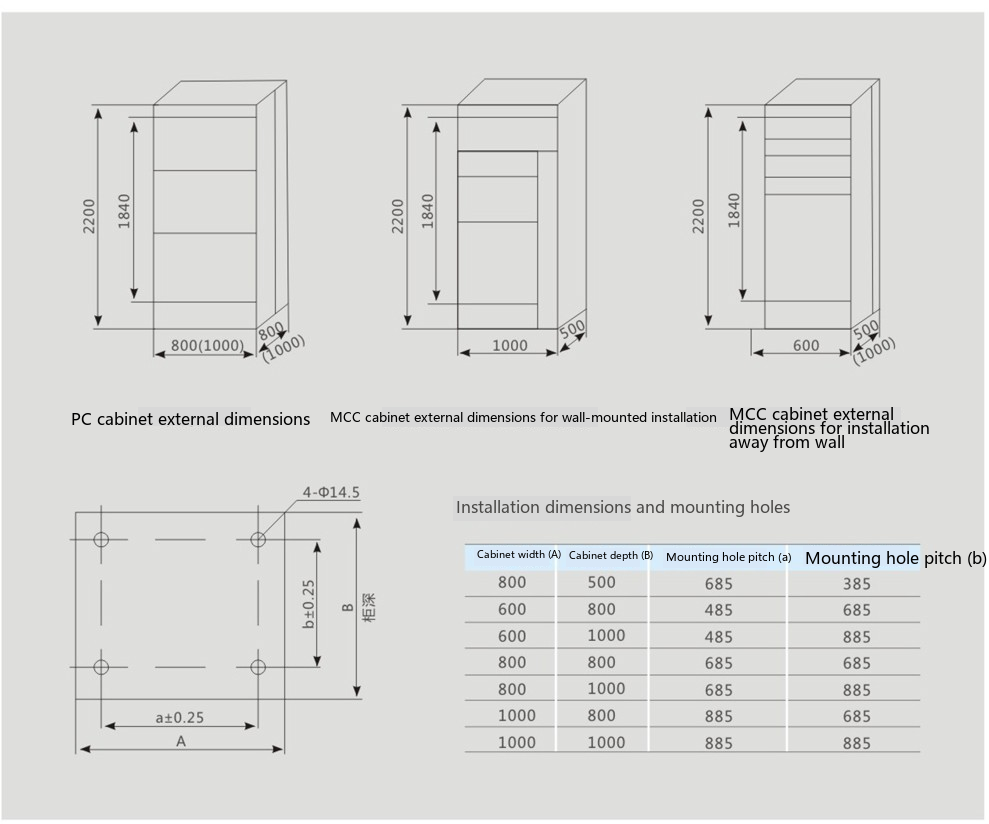
| Cabinet Width (A) |
Cabinet Depth (B) |
Mounting Hole Pitch (a) |
Mounting Hole Pitch (b) |
| 800 | 500 | 685 | 385 |
| 600 | 800 | 485 | 685 |
| 600 | 1000 | 485 | 885 |
| 800 | 800 | 685 | 685 |
| 800 | 1000 | 685 | 685 |
| 1000 | 800 | 885 | 685 |
| 1000 | 1000 | 885 | 885 |
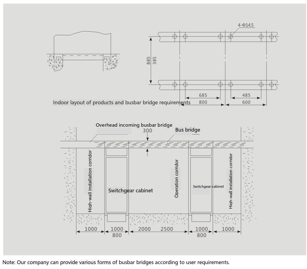
Product Installation Foundation Diagram
Special Notes
- The door of this product is interlocked with the main switch, meaning the door can only be opened when the power is off. The other sides of this product are screw-sealed plates and are not interlocked with the main switch. Therefore, please ensure the power is disconnected when opening the side plates for maintenance.
- During installation, the horizontal connections between cabinets must be secure and reliable.
- Non-professionals should not open the cabinet for maintenance or repair.
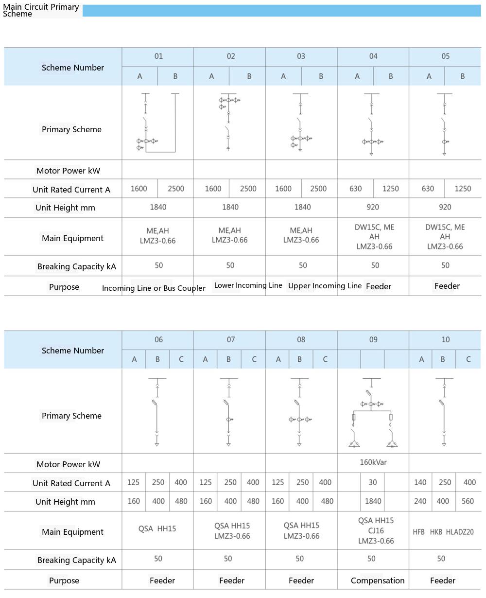
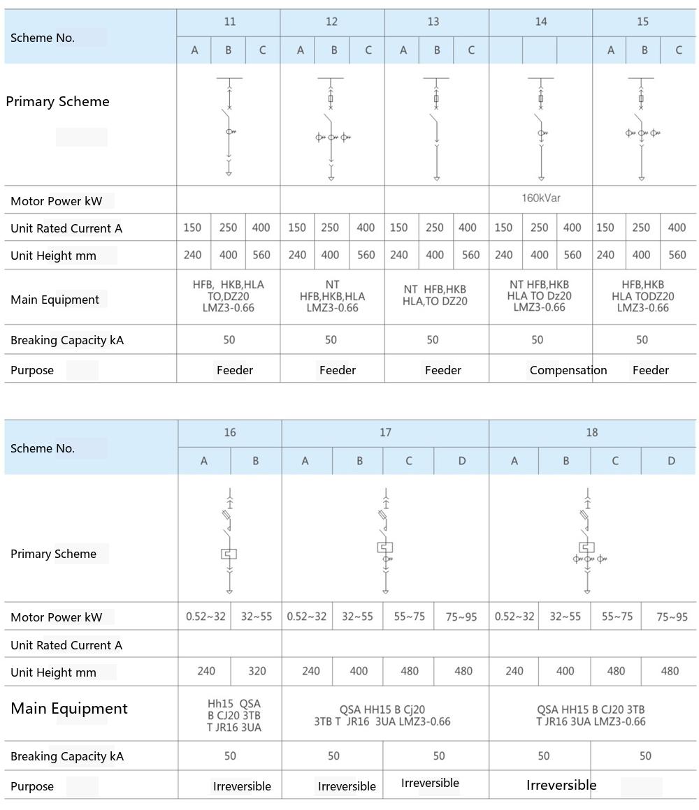
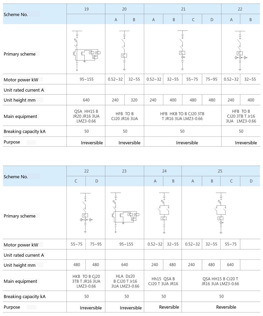
Single-Line Main Circuit Schemes
GCK Low-voltage Withdrawable Switchgear | Low-voltage Complete Distribution Equipment Power Distribution and Motor Control Center