
High Voltage Vacuum Circuit Breaker
Product Title
Product Details
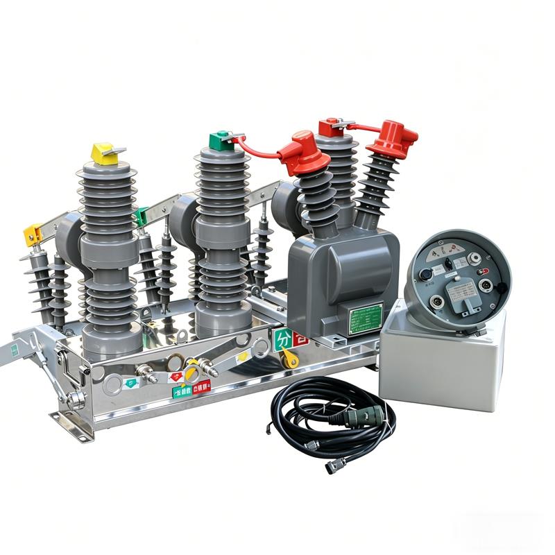
ZW32-12FG/630-20 Outdoor Watchdog Vacuum Circuit Breaker Main applications and scope of use
When a fault occurs inside a user connected to a 10kV overhead distribution line via a T-junction, if the fault is on the incoming line section, or if the fault occurs inside the user's incoming switch but the protection operation time coordination with the substation outgoing switch protection is improper, it will cause the substation outgoing switch protection to trip. If the fault is permanent and the substation reclosing fails, an accident within a medium-voltage user's boundary will cause a power outage on the entire distribution line.
The ZW32-12F User Boundary Switch is a device designed to solve the above propagation accidents. Installed at the responsibility boundary point of 10kV overhead distribution lines, it can automatically remove single-phase earth faults and automatically isolate phase-to-phase short-circuit faults, ensuring the power safety of non-faulty users.
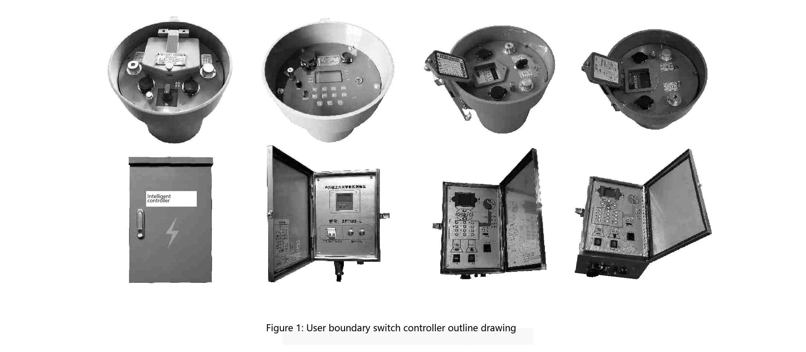
The user boundary switch controller is specially designed for intelligent control of the boundary switch body, implementing protection control functions and communication functions. The controller and the switch body are electrically connected through control cables and aviation connectors, realizing its protection and automatic monitoring functions. This product is widely applicable to users of 10kV overhead distribution lines in urban and rural areas. See Figure 1 for appearance.
Product Quality Responsibility: Before putting the ZW32-12F/630-20 controller into operation, please read this manual carefully. We assume no responsibility for equipment damage caused by improper operation.
Controller Features
Structural Features
a) The controller is a microcomputer-based relay protection and monitoring device;
b) The controller has strong weather resistance and anti-condensation protection;
c) Connected to the switch body via aviation connectors; d) Good connection reliability and high protection level.
The controller has four analog input channels: A-phase current, C-phase current, zero-sequence current, and BC phase-to-phase voltage. The controller determines line faults by monitoring the values of the above analog quantities in real time and comparing them with the set values, thereby performing corresponding processing. The table below shows the fault handling results for different systems.
| Fault Type and Fault Point | Protection Action | |
|---|---|---|
| Single-phase Earth Fault | Neutral ungrounded system - within user boundary Neutral grounded via arc suppression coil - within user boundary |
Trips after delay determining permanent earth fault |
| Neutral ungrounded system - outside user boundary Neutral grounded via arc suppression coil - outside user boundary |
No action | |
| Neutral grounded via low resistance - within user boundary | Trips before substation protection operates | |
| Neutral grounded via low resistance - outside user boundary | No action | |
| Phase-to-phase Short-circuit Fault | Within user boundary | Generally trips before substation boundary switch |
| Outside user boundary | No action | |
Pole-mounted Installation Diagram
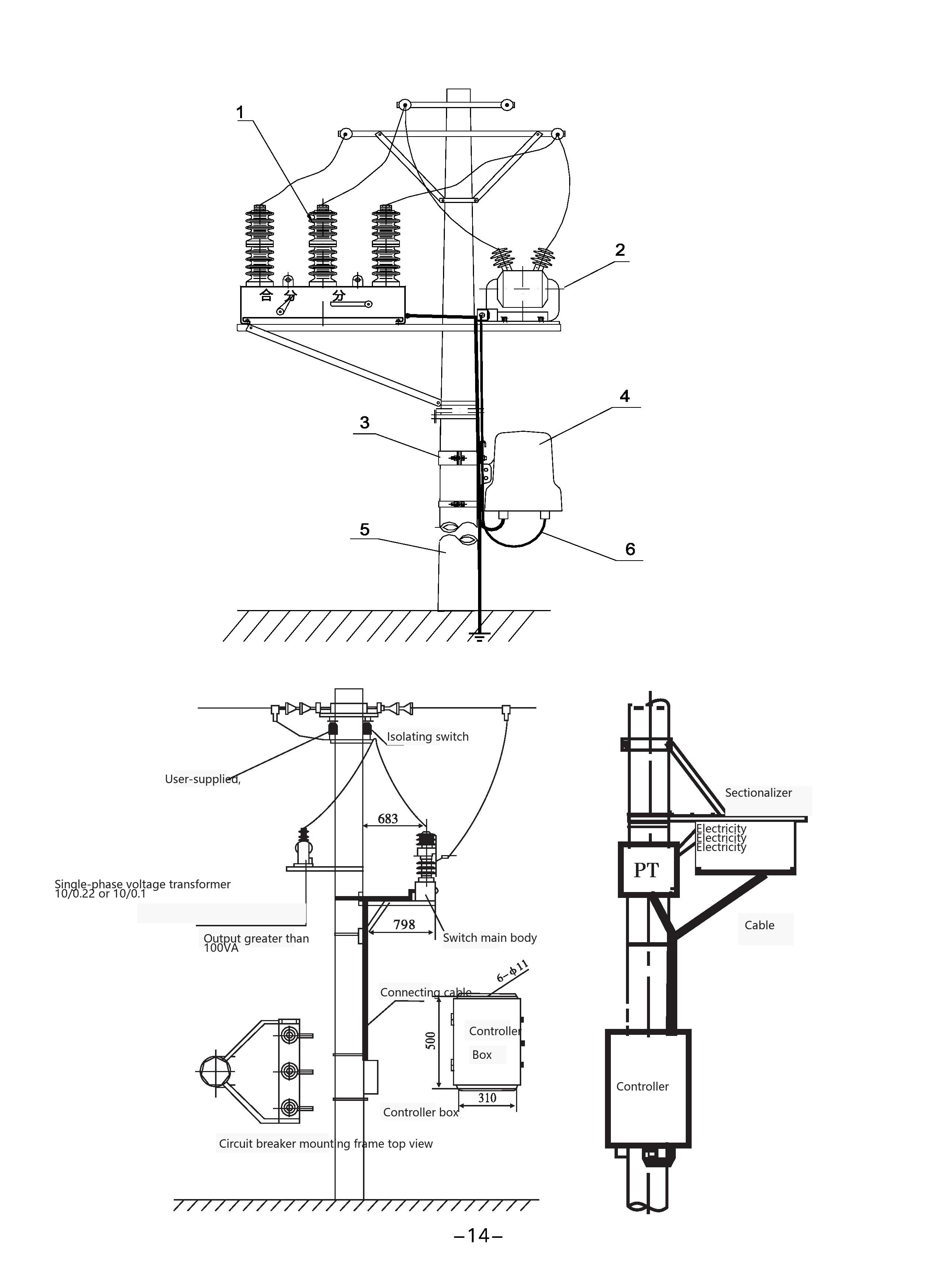
The ZW32-12F boundary switch body and controller are installed on the same pole. The connection diagram is shown in Figure 2:
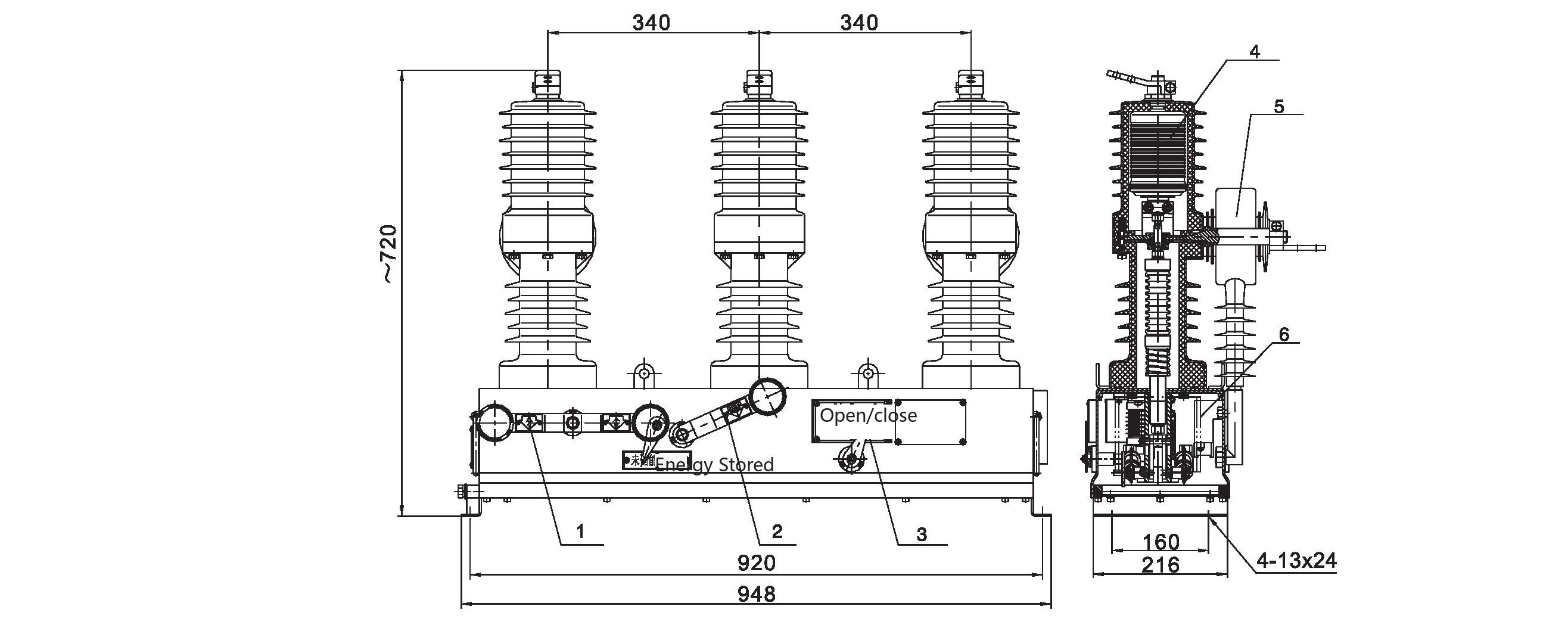
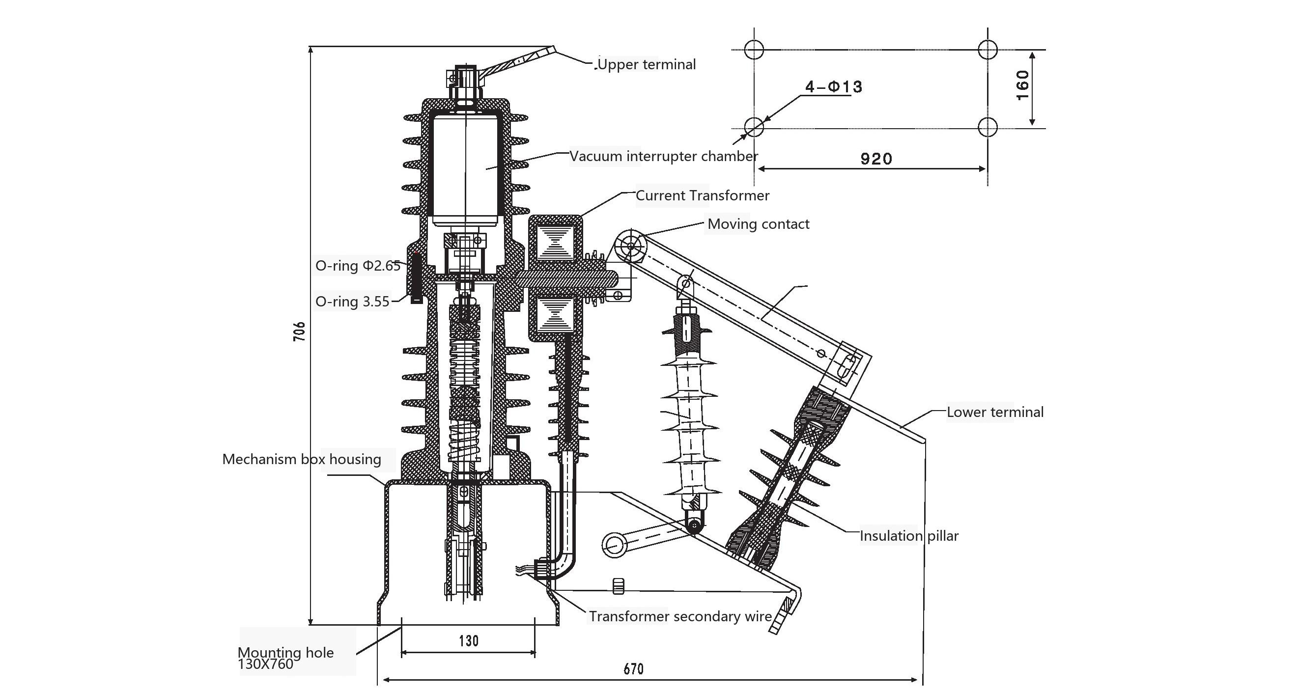
Figure 1: Circuit Breaker Outline and Installation Dimensions
B Button: Unlock; A Button: Open; D Button: Close;
For remote control operation, press B button for 1 second first, then press the function button within 3 seconds;
For example: For opening operation, press B button for 1 second first, then press A button within 3 seconds;
For closing operation, press B button for 1 second first, then press D button within 3 seconds.
Device Search
Select 'Device Search', the PDA will search for controllers within communication range (open area distance less than 150 meters). If controllers are found within the search range, select the device number of the corresponding controller to enter the main interface window displaying the selected device number.
Status Query
Select 'Status Query', the display result will be the real-time status values of the current controller.
Record Query
Select 'Record Query' to display the 30 most recent fault records that have occurred;
Remote Control Operation
Select the 'Remote Control Operation' window to display the selection interface.
Select 'Switch Close' to remotely control the controller with the corresponding device number to perform one closing operation;
Select 'Switch Open' to remotely control the controller with the corresponding device number to perform one opening operation;
Modify Settings
Select 'Modify Settings' to modify all setting parameters of the controller.
Device Reset
'Device Reset' can remotely control the FDR-2GP controller to perform a reset operation.
Transportation
During transportation, the switch body and controller must be placed in a closed packing case and fixed. Acceptance
7.2.1 Check whether the controller packaging is damaged.
7.2.2 Check whether the documents are complete and whether the accessories and spare parts are complete against the product packing list.
7.2.3 Check whether the technical parameters on the nameplate meet the order requirements.
Storage
This controller should be stored indoors in a dry, ventilated, moisture-proof, shock-proof place protected from harmful gas intrusion. For long-term storage, regularly check whether the environment meets the requirements. Packing, unpacking and storage should be carried out in a dry indoor environment, and the product and its components should be checked for completeness and consistency. The stacking height of the product body should not exceed 3 layers.
The equipment has undergone strict factory tests. If any abnormality is found during use, please record the factory serial number of the equipment and the abnormal issues and contact us.
Special Note: Do not disassemble, modify or repair the equipment without authorization.
Possible faults that may occur during use are listed below. In the event of an accident, if the switch malfunctions, the following handling methods are provided for reference during use.
| Fault | Fault Phenomenon | Handling Method |
|---|---|---|
| Intermittent component failure or deterioration due to long-term use | Due to long-term use, intermittent or long-term deterioration may cause component failure | Replace with spare parts so that rapid replacement is possible in case of failure. |
| Surge voltage fault | When excessive surge voltage such as lightning is applied, the contacts of the switch closing relay or the protective arrester may burn out. | Install distribution line arresters and check that the equipment grounding is single-point grounded. |
ZW32-12F/630-20_Outdoor Watchdog Vacuum Circuit Breaker_10kV Overhead Distribution Line Boundary Protection

Telephone

Online Service

Follow Us


TikTok

Back to Top


