
High Voltage Vacuum Circuit Breaker
Product Title
Product Details
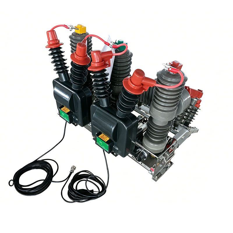
ZW32-12FG/630A Primary-secondary Fusion Outdoor Pole-mounted Vacuum Circuit Breaker is a new generation product developed by our company in response to the new requirements of State Grid for primary-secondary fusion integrated pole-mounted switches. The switch configuration fully complies with State Grid primary-secondary fusion integrated requirements, facilitating unified procurement and mass production by State Grid. The ZW32-12FG switch has compact structure, reasonable layout, complete functions, and all indicators meet State Grid primary-secondary fusion requirements. It adopts protection CT, zero-sequence CT and zero-sequence voltage sensors with unified parameters, featuring wide measurement range, high measurement accuracy and high reliability. Complete analog quantities facilitate accurate determination of various line faults.
The ZW32-12 switch body is of post-type design, using solid-sealed vacuum interrupters with silicone rubber encapsulation (as insulation and buffer), small size, encapsulated in epoxy resin insulating cylinders, excellent anti-condensation performance, long service life and reliable performance. Its spring operating mechanism has been miniaturized and performance-optimized, with operational reliability far higher than traditional domestic spring mechanisms. Complies with environmental requirements: oil-free and SF6-free, high pollution resistance level, aesthetically pleasing, lightweight, easy to transport. The primary-secondary fusion outdoor pole-mounted vacuum circuit breaker is equipped with 1 set of external EVT and ECT (three-phase voltage, current, zero-sequence voltage and current for measurement, metering and protection).
Table 1 Electrical Technical Parameters
| Item | Parameter |
|---|---|
| Rated Voltage | 12kV |
| Rated Frequency | 50Hz |
| Rated Current | 630A |
| Rated Short-time Withstand Current | 20kA |
| Rated Short-time Withstand Current Duration | 4s |
| Rated Short-time Withstand Current (Peak) | 20kA |
| Rated Short-circuit Making Current (Peak) | 63kA |
| Rated Cable Charging Current | 25A |
| Rated Short-circuit Breaking Current | 20kA |
| Rated Operating Sequence | Open-0.3s-Close-Open-180s-Close-Open |
| Isolating Gap Insulation Level | Power Frequency (Dry test): 48kV |
| Lightning Impulse Test Voltage (Peak): 85kV | |
| To Earth and Between Phases Insulation Level | Power Frequency (Dry): 42kV |
| Power Frequency (Wet): 34kV | |
| Lightning Impulse Test Voltage (Peak): 75kV | |
| Rated Mechanical Stability Times | Circuit breaker: 10000 times (M2 level) |
| Rated Opening/Closing Operating Voltage (V) | DC24V |
| Total Weight | 150kg |
| Outline Dimensions (L×W×H) | |
| Closing Time | 20~60ms |
| Opening Time | 18~45ms |
| Closing Non-synchronism (ms) | ≤2 |
| Opening Non-synchronism (ms) | ≤2 |
| Average Closing Speed (m/s) | 0.4~0.8 |
| Average Opening Speed (m/s) | 0.8~1.2 |
| Contact Gap (mm) | 9±1 |
| Contact Overtravel (mm) | 2±0.5 |
| Contact Closing Bounce Time (ms) | ≤2 |
Charging motor power not exceeding 40W, charging and operating voltage DC24V, facilitating backup power installation.
1. Circuit Breaker Body
The circuit breaker consists of vacuum interrupters, operating mechanism and supporting components, adopting a three-phase post-type fully enclosed structure.
2. Operating Mechanism and Working Principle
1) The circuit breaker can adopt an electric operating mechanism.
2) Working Principle
The circuit breaker is operated by the operating mechanism, driving the output crank arm and three-phase transmission rod to close the switch. After the circuit breaker closes, pull the manual opening ring or apply voltage to the opening coil, and the transmission rod driven by the opening spring causes the circuit breaker to open.
During operation, when the line current exceeds the set value, the overcurrent coil operates, causing the opening half-shaft to rotate and the circuit breaker to open, thereby protecting the line and equipment.
3. Matching Aviation Socket
The switch body unit is equipped with one 26-core aviation socket.
Table 2 26-core Aviation Socket and Plug Pin Definitions
| Switch Side Connector Pin | For Spring Mechanism Switch | For Permanent Magnetic Mechanism Switch | For Electromagnetic Mechanism Switch | Diagram | |||
|---|---|---|---|---|---|---|---|
| Mark | Description | Mark | Description | Mark | Description | ||
| 1 | CN- | Charging- | -- | -- | -- | -- | 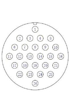 |
| 2 | CN+ | Charging+ | -- | -- | -- | -- | |
| 3 | HZ- | Closing- | HZ- | Closing-/Coil- | HZ- | Closing- | |
| 4 | HZ+ | Closing+ | HZ+ | Closing+/Coil+ | HZ+ | Closing+ | |
| 5 | FZ- | Opening- | FZ- | Opening- | -- | -- | |
| 6 | FZ+ | Opening+ | FZ+ | Opening+ | -- | -- | |
| 7 | Ia | Phase A Current | Ia | Phase A Current | Ia | Phase A Current | |
| 8 | Ib | Phase B Current | Ib | Phase B Current | Ib | Phase B Current | |
| 9 | Ic | Phase C Current | Ic | Phase C Current | Ic | Phase C Current |
| 10 | In | Phase Current Common | In | Phase Current Common | In | Phase Current Common |
| 11 | IO | Zero-sequence Current | IO | Zero-sequence Current | IO | Zero-sequence Current |
| 12 | IOcom | Zero-sequence Current Common | IOcom | Zero-sequence Current Common | IOcom | Zero-sequence Current Common |
| 19 | YXCOM | Telemetry Common | YXCOM | Telemetry Common | YXCOM | Telemetry Common |
| 20 | HW | Closed Position | HW | Closed Position | HW | Closed Position |
| 21 | FW (Optional) | Open Position | FW | Open Position | FW (Optional) | Open Position |
| 22 | WCN | Uncharged Position | -- | -- | -- | -- |
| 23 | U0 | Zero-sequence Voltage | U0 | Zero-sequence Voltage | U0 | Zero-sequence Voltage |
| 24 | U0com | Zero-sequence Voltage Common | U0com | Zero-sequence Voltage Common | U0com | Zero-sequence Voltage Common |
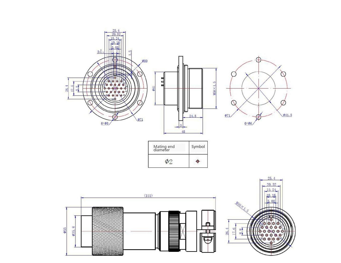 Figure 5 26-core Aviation Plug and Socket Dimensions
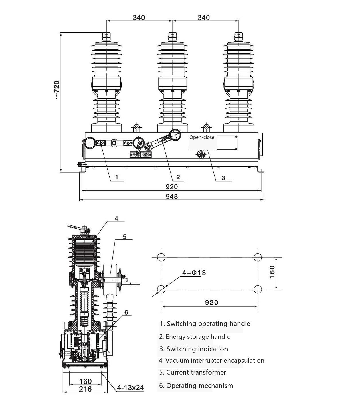 Figure 5(1) Circuit Breaker Outline and Installation Dimensions
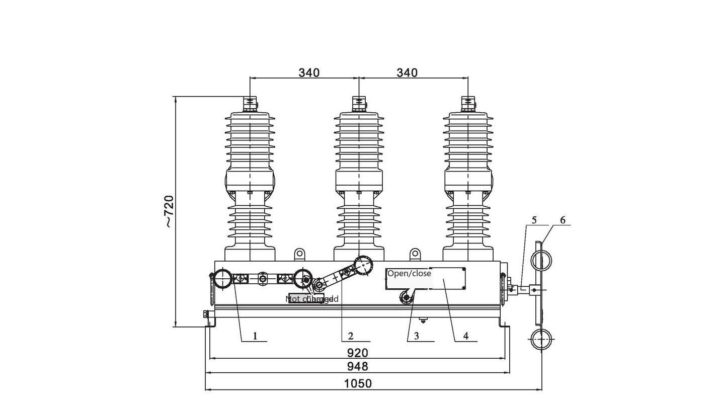
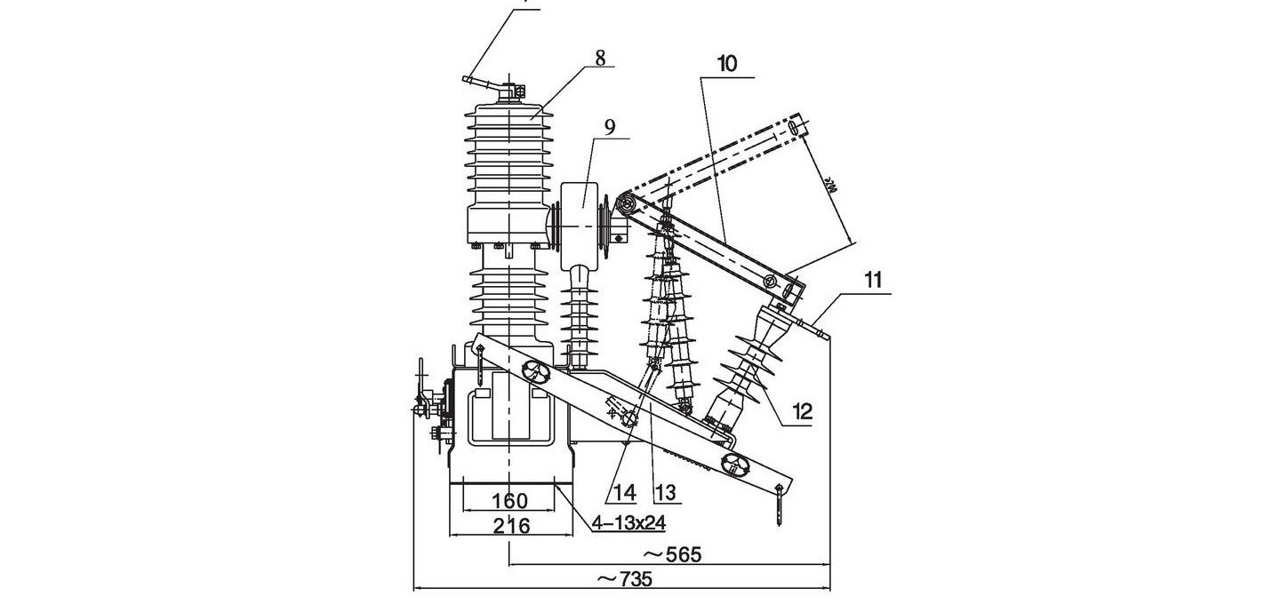
Figure 5(2) Vacuum Circuit Breaker (with Isolating Switch) Outline and Installation Dimensions
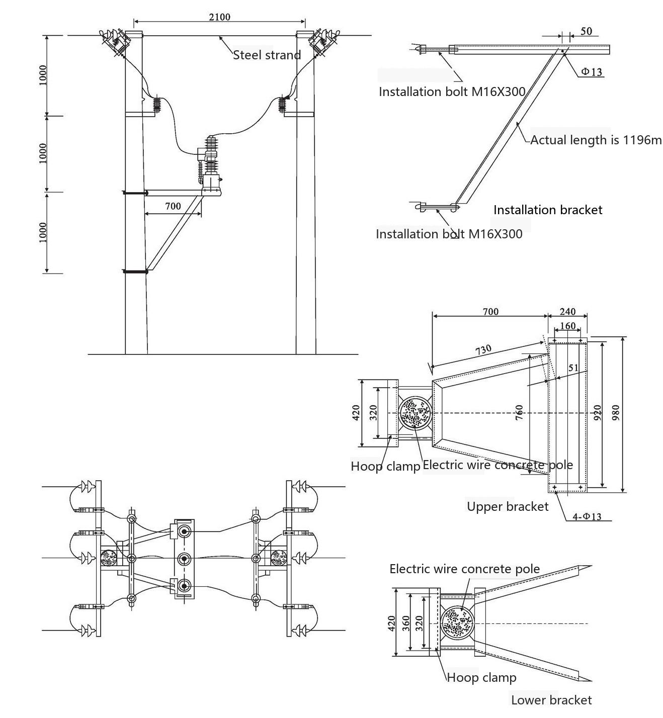 Note: Hoop size customized according to actual pole diameter Figure 6(1) Vacuum Circuit Breaker Double-pole Installation Diagram
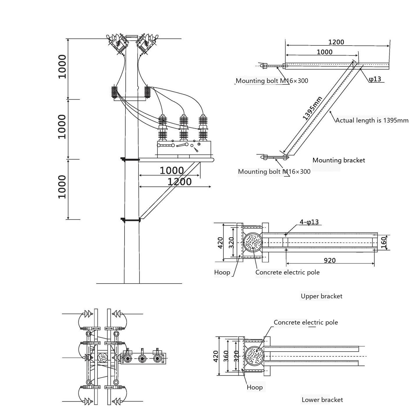 Note: Hoop size customized according to actual pole diameter Figure 6(2) Vacuum Circuit Breaker Single-pole Installation Diagram
The factory-delivered products have been adjusted to the optimal state. Maintenance of the switch is generally limited to the following situations:
9.1 After the product has been in operation for a certain period, clean the switch bushings;
9.2 Within 2 years from the factory date, if the product fails due to manufacturing quality issues or gas leakage, the manufacturer is responsible for replacement or repair (mainly carried out at various maintenance points or maintenance centers).
10.1 Transportation
This product must be packaged before transportation. During transportation or lifting, strong vibration is not allowed, and inversion or rolling is prohibited.
10.2 Acceptance
Acceptance should be carried out according to the following procedures:
10.2.1 Unpack indoors, check whether the accompanying documents are complete against the packing list;
10.2.2 Carefully remove the switch, inspect the appearance for signs of impact damage, with special attention to whether the porcelain bushing is cracked;
10.2.3 Check whether the gauge pressure is at 0.35MPa (at 20degC) (when a pressure gauge is installed as per user requirements);
10.2.4 Perform 5 trial operations of the switch, with no refusal to close or open.
10.2.5 If conditions permit, measure the circuit resistance value (should be less than 130μΩ).
10.3 Storage
This product should be stored indoors in a place not prone to collision and with good ventilation.
12.1 Please determine the product model, name, quantity, rated current, operating power supply type, operating voltage, etc. as required.
12.2 According to user requirements, the following can be provided:
Primary-secondary Fusion Outdoor Pole-mounted Vacuum Circuit Breaker ZW32-12FG/630A|10kV Pole-mounted Switch

Telephone

Online Service

Follow Us


TikTok

Back to Top


