High Voltage Insulator
Product Title
Product Details
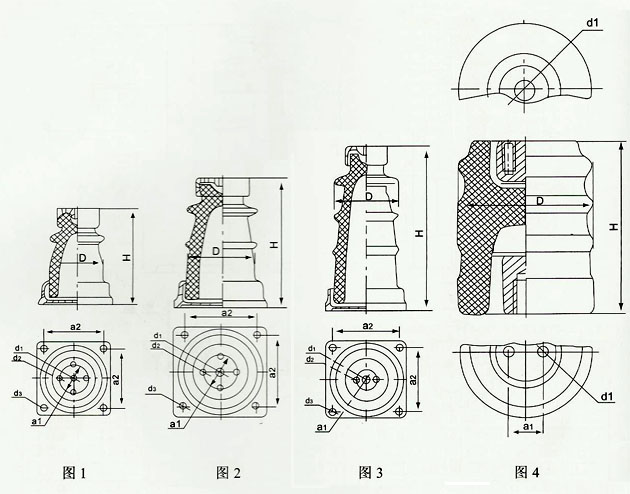
Indoor post insulators are used for insulation and fixing of conductive parts in indoor substations, switchgear, and electrical equipment with rated voltages of 6~35kV.
The insulators are suitable for ambient temperatures of -40C~+40C. The altitude for standard type installation does not exceed 1000m, and for plateau type does not exceed 4000m.
Insulators are classified into three structural types according to the cementing structure: external cementing, internal cementing, and combined cementing. Insulators are classified by rated voltage and bending strength as follows:
Rated Voltage kV | Bending StrengthkN | ||
External Cementing | Internal Cementing | Combined Cementing | |
6 | 3.75, 7.5 | 4 | - |
10 | 3.75, 7.5, 20 | 4, (7), 8, 16 | 4 |
20 | 20 | - | 30 |
35 | - | (7.5) | 4, (7.5), 8 |
Note: () in the table indicates non-standard grades
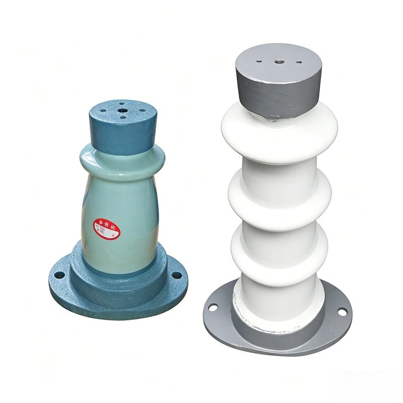
The insulator is composed of a porcelain body and upper and lower metal fittings cemented together with adhesive. Elastic gaskets are placed between the end faces of the porcelain body and the cemented contact parts of the metal fittings. The cemented parts of the porcelain body adopt structures such as sanding, knurling, and grooving to ensure mechanical strength and prevent loosening and torsion. The surface of the porcelain body is evenly glazed white, and the surface of the metal fittings is coated with gray enamel paint.
The main body of the insulator porcelain has two structures: hollow with a partition (puncture-proof type) and solid (non-puncture-proof type). Combined cementing post insulators generally have a solid non-puncture-proof structure. The latter structure improves safety and reliability compared to the former and reduces maintenance testing workload.
The porcelain body shape can be multi-ribbed or few-ribbed. The multi-ribbed shape increases the surface creepage distance and has better electrical performance than the few-ribbed shape. Except for the external cementing post insulators that will be gradually phased out, all other products are multi-ribbed.
For the internal cementing structure, since the metal fittings are cemented into the porcelain holes, the insulation distance is correspondingly increased, improving electrical performance and reducing the space occupied during installation. However, since internal cementing is not beneficial for improving mechanical strength, for insulators requiring high mechanical strength, combined cementing (i.e., upper fitting with internal cementing, lower fitting with external cementing) is recommended.
Indoor post insulators are manufactured according to national standards GB8287.1~8287.2 "High-voltage Post Porcelain Insulators".
Z--Indoor/outdoor cemented post insulator;
ZN--Indoor internal cementing post insulator;
ZL--Indoor combined cementing post insulator;
For external cementing post insulators, the letter L before the dash indicates multi-ribbed type, and letters A, B, D indicate mechanical failure loads of 3.75, 7.5, and 20kN respectively. The fraction after the letter indicates: numerator - rated voltage in kV, denominator - mechanical failure load in kN.
N--Internal cementing with single threaded hole for upper and lower fittings;
Y--External cementing and combined cementing with circular lower fitting;
T--External cementing with elliptical lower fitting;
F--External cementing with square lower fitting;
G--Plateau type (GY for older products)
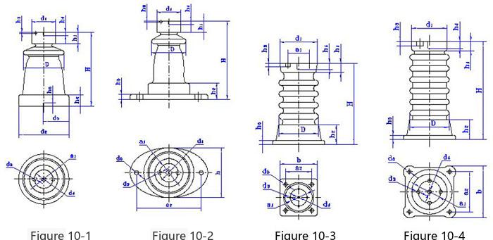
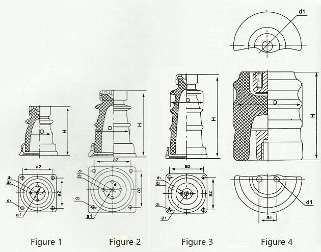
Model | Figure No. | Main Dimensionsmm | Weightkg | |||||||||||||
H | D | h1 | h2 | h3 | h4 | h5 | d1 | d2/b | d3 | d4 | d5 | a1 | a2 | |||
ZA-6Y | 10-1 | 165 | 86 | 27 | 36 | 6 | 13 | 20 | 62 | 106 | 2-M6 | M10 | M12 | 36 | - | 2.1 |
ZA-6T | 10-2 | 165 | 86 | 27 | 36 | 6 | 13 | 10 | 62 | 110 | 2-M6 | M10 | 2-Φ12 | 36 | 135 | 2.3 |
ZB-6Y | 10-1 | 185 | 106 | 38 | 48 | 7 | 18 | 22 | 82 | 129 | 2-M10 | M16 | M16 | 46 | - | 4.2 |
ZB-6T | 10-2 | 185 | 106 | 38 | 46 | 7 | 18 | 12 | 82 | 140 | 2-M10 | M16 | 2-Φ15 | 46 | 175 | 4.9 |
ZA-10Y | 10-1 | 190 | 86 | 27 | 36 | 6 | 13 | 20 | 66 | 110 | 2-M6 | M10 | M12 | 36 | - | 2.25 |
ZA-10T | 10-2 | 190 | 86 | 27 | 36 | 6 | 13 | 10 | 62 | 110 | 2-M6 | M10 | 2-Φ12 | 36 | 135 | 2.5 |
ZB-10Y | 10-1 | 215 | 106 | 38 | 48 | 7 | 18 | 22 | 82 | 129 | 2-M10 | M16 | M16 | 46 | - | 4.6 |
ZB-10T | 10-1 | 215 | 106 | 38 | 46 | 7 | 18 | 12 | 82 | 140 | 2-M10 | M16 | 2-Φ15 | 46 | 175 | 5.24 |
ZLD-10F | 10-3 | 215 | 110 | 46 | 65 | 14 | 22 | 18 | 160 | 160 | 4-M12 | M16 | 4-Φ15 | 76 | 125 | 9.5 |
10kv/3.75kN | 10-1 | 190 | 110 | 27 | 36 | 6 | 13 | 20 | 66 | 110 | 2-M6 | M10 | M12 | 36 | - | 2.8 |
10kv/7.5kN | 10-2 | 215 | 126 | 38 | 48 | 7 | 18 | 12 | 82 | 135 | 2-M10 | M16 | 2-Φ15 | 46 | 175 | 6.0 |
10kV/20kN | 10-3 | 215 | 110 | 46 | 65 | 14 | 22 | 18 | 160 | 192 | 4-M12 | M16 | 4-Φ15 | 76 | 155 | 10.9 |
10kv/20kN | 10-3 | 215 | 110 | 46 | 65 | 14 | 22 | 18 | 160 | 160 | 4-M12 | M16 | 4-Φ15 | 76 | 125 | 10.9 |
ZLD-20F | 10-4 | 315 | 143 | 46 | 80 | 14 | 22 | 18 | 128 | 195 | 4-M12 | M18 | 4-Φ18 | 76 | 155 | 16 |
Model | Rated VoltagekV | Power Frequency VoltagekV r.m.s≥ | Full Wave Impulse Withstand VoltagekV peak≥ | Bending and Tensile Failure LoadkN ≥ | Nominal Creepage Distancemm | |
Dry Withstand | Breakdown | 60 | ||||
ZA-6Y | 6 | 36 | 58 | 60 | 3.75 | - |
ZA-6T | 6 | 36 | 58 | 60 | 3.75 | - |
ZB-6Y | 6 | 36 | 58 | 60 | 7.50 | - |
ZB-6T | 6 | 36 | 58 | 80 | 7.50 | - |
ZA-10Y | 10 | 47 | 75 | 80 | 3.75 | - |
ZA-10T | 10 | 47 | 75 | 80 | 3.75 | - |
ZB-10Y | 10 | 47 | 75 | 80 | 7.50 | - |
ZB-10T | 10 | 47 | 75 | 80 | 7.50 | - |
ZLD-10F | 10 | 47 | 75 | 80 | 20 | - |
10kv/3.75kN | 10 | 47 | 75 | 80 | 3.75 | - |
10kv/7.5kN | 10 | 47 | 75 | 80 | 7.50 | 230 |
10kV/20kN | 10 | 47 | 75 | 80 | 20 | 230 |
10kv/20kN | 10 | 47 | 75 | 80 | 20 | Both upper and lower flanges are ductile iron |
ZLD-20F | 20 | 75 | - | 125 | 20 | - |
| ||||||||||||||||||||||||||||||||||||||||||||||||||||||||||||||||||||||||||||||||||||||||||||||||||||||||||||||||||||||||||||||||||||||||
ZA Series Indoor and Outdoor Cemented Post Insulator | High and Low Voltage Switchgear Cemented Post Insulator

Telephone

Online Service

Follow Us


TikTok

Back to Top