
High Voltage Disconnecting Switch
Product Title
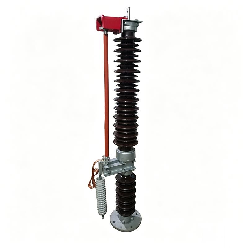
Product Details
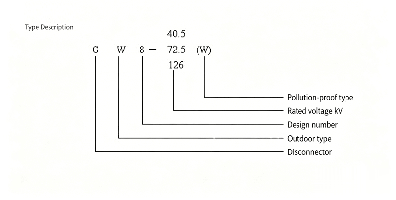
GW8 neutral point disconnecting switch is a single-phase AC 50Hz high voltage switchgear, rated current: 630A, 1250A. Used for making and breaking transformer neutral point earthing lines under voltage and no-load conditions. GW8 Neutral Point Outdoor High Voltage Disconnecting Switch is also used for railway automatic blocking signal devices and can be used as single pole. The anti-pollution type can meet the requirements of heavy pollution areas and effectively solve the pollution flashover problem during operation.
This product is available in standard type and anti-pollution type (W); the operating mechanisms used with this product are: CS8-5 manual operating mechanism or CX6 electric operating mechanism; CS17-G manual operating mechanism or CJ2, CJ5, CJ6, CJ12 electric operating mechanisms.
Service Environment
This series of disconnecting switches meets all requirements specified in GB1985-89 "AC High Voltage Disconnecting Switches", IEC129 (1984) "AC Disconnecting Switches and Earthing Switches" and IEC694 (1980) "Common Clauses for High Voltage Switchgear and Controlgear".
| Item | GW8-40.5G | GW8-72.5G | GW8-126G |
| Rated Voltage (kV) | 40.5 | 72.5 | 126 |
| Voltage (kV) | 40.5 | 40.5 | 126 |
| Rated Current (A) | 630, 1250 | 630, 1250 | 630, 1250 |
| Rated Peak Withstand Current (kA) | 50, 80 | 50, 80 | 50, 80 |
| Rated Short-time Withstand Current (kA) | 20, 31.5 | 20, 31.5 | 20, 31.5 |
| 1min Power Frequency Withstand Voltage (kV) | 90 | 155 | 230 |
| Terminal Rated Static Tension (N) | 500 | 500 | 500 |
Principle and Structure
This disconnecting switch (see Figure 1 for outline) consists of base, post insulators and conductive parts. Fixed contacts and terminal blocks for busbar connection are installed on top of the insulating supports. Between the post insulators and insulating supports are the base, moving contact, operating crank arm, operating insulator. The operating mechanism is connected to the moving contact through connecting rods, operating insulator and operating crank arm.
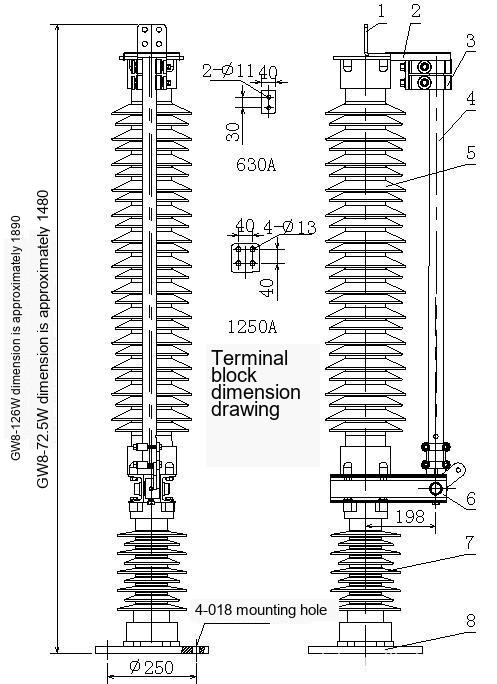
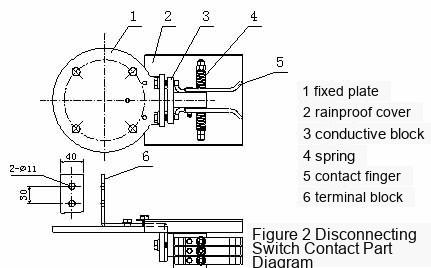
The disconnecting switch contacts (see Figure 2) consist of one pair (for 630A) or two pairs (for 1250A) of identical self-contained copper alloy contact fingers, springs and spring seats. The gap between contact fingers should be 27±2mm. If not met, adjustment can be made by adjusting the shims between contact fingers. Except for the sliding line contact at the gap, all other conductor connections in the entire conductive circuit are fixed connections, with small contact resistance, simple structure and reliable operation. The contacts are bent from copper plates with large connection area with the conductive rod. During opening and closing, the friction travel between contact and contact finger is short, resulting in small operating force. The contact finger springs are made of high-quality stainless steel and are externally pressurized to avoid spring current sharing.
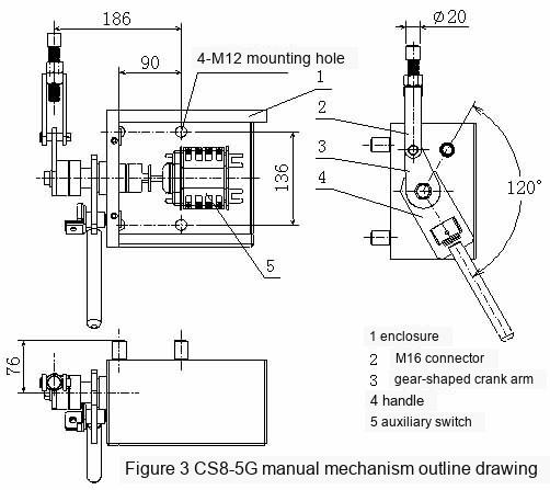
CS8-5G manual operating mechanism (see Figure 3) is rain-proof type. The mechanism output crank arm does not require drilling for taper pins and can be automatically positioned. The number of auxiliary switch poles in the mechanism is determined by the user's order contract. If not specified, it is supplied with four open and four closed. For electric operating mechanism, see separate manual.
Outline Dimensions Assembly Drawing
GW8 series neutral point high voltage disconnecting switch assembly drawing (with CX-6 electric operating mechanism)
Installation and Commissioning
After installing the disconnecting switch and mechanism according to assembly drawing 4, place both the disconnecting switch body and mechanism in the closed position (operating handle downward when mechanism is in closed position). Connect the disconnecting switch and mechanism using operating insulator, connectors and water gas pipe, with crank arm angle as shown. Adjust connector length so that the disconnecting switch closes reliably when the mechanism is in open and closed positions, and the insulation distance meets requirements. Note that during initial closing, the deviation of the moving contact from the fixed contact center line should not exceed 5mm; otherwise, adjustment can be made by adding or removing shims under the insulator lower part and adjusting the shims at both ends of the crank arm.
Ensure that during maintenance of GW8 Neutral Point Outdoor High Voltage Disconnecting Switch... GW8-40.5/72.5kV neutral point disconnecting switch installation requires operating mechanism verticality deviation ≤2deg, neutral point lead wire cross-section selected based on maximum earthing current, discharge gap distance set according to system insulation coordination and recorded.
GW8 Neutral Point Outdoor High Voltage Disconnecting Switch GW8-40.5 72.5kV/630A

Telephone

Online Service

Follow Us


TikTok

Back to Top


