
High Voltage Complete Switchgear Cabinet
Product Title
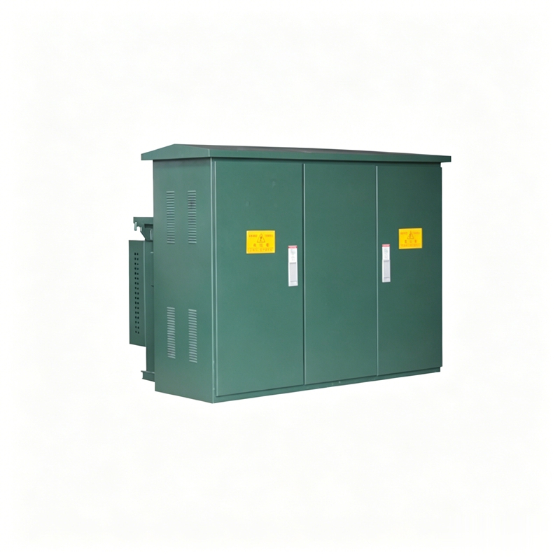
Product Details
This product is developed by absorbing foreign technology and combining it with domestic实际情况. The entire product features small size, simple installation and maintenance, low noise, low loss, anti-theft, strong overload capacity, and full protection. It is suitable for new residential communities, green belts, parks, station hotels, construction sites, airports, and other locations.
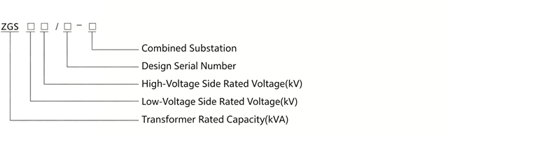
The ZGS□-12 combined substation (American-type) is suitable for 10kV loop network power supply, dual power supply, or terminal power supply systems, serving as a transformation, metering, compensation control, and protection device.
◇ Fully insulated, fully sealed, minimal to no maintenance, reliably ensuring personal safety;
◇ Compact structure, volume only 1/3 to 1/5 of a European-type substation of the same capacity, with low height;
◇ Can adopt a split-tank structure to avoid oil contamination within the transformer tank;
◇ High-voltage side uses dual fuse full-range protection, significantly reducing costs;
◇ Can be used for both loop network and terminal applications. Cable connectors can be emergency plugged and unplugged at 200A load current;
◇ Enclosure uses honeycomb double-layer composite panels, providing both heat insulation and heat dissipation;
◇ Low-voltage side is equipped with an electronic phase failure protector. When abnormal voltage appears in the system, it can quickly trip the main incoming switch;
◇ High-voltage side oil-immersed load switch or SF6 load switch can be upgraded electrically, laying the foundation for distribution network automation.
◇ Uses oil-immersed S9 or higher-performance S11 series transformers.
◇ Altitude not exceeding 1000m;
◇ Ambient temperature: -35C~+40C;
◇ Relative humidity: daily average not more than 95%, monthly average not more than 90%;
◇ Installation site: free from fire, explosion hazards, chemically corrosive gases, and well-ventilated, with ground inclination not more than 3deg.
GB/T 17467-1998 "High-voltage/Low-voltage Prefabricated Substations"
DL/T 537-93 "Technical Conditions for Ordering 6-35KV Compact Substations"
◇ Combined Substation Technical Parameters
| No. | Item | Unit | Technical Parameter |
|---|---|---|---|
| 1 | Rated Voltage | kV | 10/0.4 (High/Low Voltage) |
| 2 | Operating Voltage | kV | 12 (High Voltage Side) |
| 3 | Rated Frequency | Hz | 50 |
| 4 | Rated Capacity | kVA | 150-1600 |
| 5 | 1min Power Frequency Withstand Voltage | kV | 35 |
| 6 | Lightning Impulse Withstand Voltage | kA | 75 |
| 7 | Cooling Method | Oil-immersed Self-cooling | |
| 8 | High-Voltage Backup Fuse Breaking Current | kA | 50 |
| 9 | Plug-in Fuse Breaking Current | kA | 2.5 |
| 10 | Ambient Temperature | C | -35~+40 |
| 11 | Coil Allowable Temperature Rise | K | 65 |
| 12 | No-load Tap-Changing | ±5% or ±2×2.5% | |
| 13 | Noise Level | db | 50 |
| 14 | Protection Level | IP43 |
◇ Transformer
Uses the new S9 series transformer core, featuring low loss, good overload capability, strong short-circuit withstand capability, and all fasteners are treated for protection. The higher-performance S11 series ring-type seamless silicon steel core transformer is also available.
| Capacity kVA | Voltage kV | Connection Symbol | No-load Current % | No-load Loss W | Impedance Voltage % | Load Loss W | |||||||
|---|---|---|---|---|---|---|---|---|---|---|---|---|---|
| High | Low | S9 | S10 | S11 | S9 | S10 | S11 | S9 | S10 | S11 | |||
| 50 | 10±5% or ±2×2.5% | 0.4 | Dyn11Vyno | 2.0 | 1.9 | 0.75 | 0.17 | 0.15 | 0.12 | 4.0 | 0.87 | 0.83 | 0.87 |
| 63 | 1.9 | 1.8 | 0.7 | 0.2 | 0.18 | 0.14 | 1.04 | 0.99 | 1.04 | ||||
| 80 | 1.9 | 1.7 | 0.7 | 0.25 | 0.22 | 0.175 | 1.25 | 1.2 | 1.25 | ||||
| 100 | 1.8 | 1.55 | 0.65 | 0.29 | 0.26 | 0.2 | 1.5 | 1.42 | 1.5 | ||||
| 125 | 1.7 | 1.45 | 0.65 | 0.34 | 0.3 | 0.235 | 1.8 | 1.72 | 1.8 | ||||
| 160 | 1.6 | 1.3 | 0.6 | 0.4 | 0.36 | 0.27 | 2.2 | 2.12 | 2.2 | ||||
| 200 | 1.5 | 1.2 | 0.55 | 0.48 | 0.43 | 0.33 | 2.6 | 2.5 | 2.6 | ||||
| 250 | 1.4 | 1.1 | 0.5 | 0.56 | 0.5 | 0.39 | 3.05 | 2.9 | 3.05 | ||||
| 315 | 1.4 | 1.0 | 0.45 | 0.67 | 0.29 | 0.465 | 3.65 | 3.45 | 3.65 | ||||
| 400 | 1.3 | 1.0 | 0.4 | 0.8 | 0.71 | 0.56 | 4.0 | 4.3 | 4.15 | 4.3 | |||
| 500 | 1.2 | 1.0 | 0.4 | 0.96 | 0.85 | 0.67 | 4.0 | 5.15 | 4.82 | 5.15 | |||
| 630 | 1.1 | 0.8 | 0.4 | 1.2 | 1.6 | 0.81 | 4.5 | 6.2 | 5.86 | 6.2 | |||
| 800 | 1.0 | 0.7 | 0.35 | 1.4 | 1.23 | 0.98 | 4.5 | 7.5 | 7.2 | 7.5 | |||
| 1000 | 1.0 | 0.6 | 0.3 | 1.7 | 1.5 | 1.15 | 4.5 | 10.3 | 9.8 | 10.3 | |||
| 1250 | 0.9 | 0.6 | 0.27 | 1.95 | 1.72 | 1.36 | 4.5 | 12.0 | 12.2 | 12.0 | |||
◇ Load Switch
The load switch is oil-immersed, three-phase linked, with a spring operating mechanism. It can be operated with load for making and breaking, and its opening/closing speed is independent of the operating force. Types include two-position, four-position T-type, four-position V-type, etc., for selection.
| Name | Unit | 315A | 630A | |
|---|---|---|---|---|
| Rated Voltage | kV | 12 | 12 | |
| Maximum Current | A | 315 | 630 | |
| Rated Frequency | Hz | 50 | 50 | |
| Rated Short-circuit Making Current | kA | 31.5 | 50 | |
| Rated Short-time Withstand Current | kA | 12.5 | 50 | |
| Rated Short-time Withstand Duration | S | 2 | 2 | |
| Mechanical Life | times | 2000 | 2000 | |
| Lightning Impulse Test | Phase to Phase/Earth | kV | 75 | 75 |
| Isolating Gap | kV | 85 | 85 | |
| 1min Power Frequency Withstand Voltage | Phase to Phase/Earth | kV | 42 | 42 |
| Isolating Gap | kV | 48 | 48 | |
| Rated Peak Withstand Current | kA | 31.5 | 50 | |
◇ Fuse
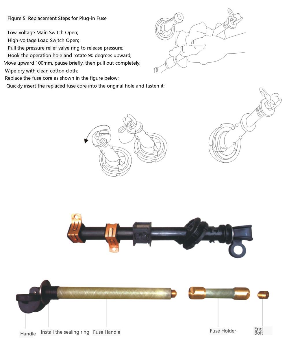
The high-voltage side of the American-type compact substation is protected by a backup fuse and a plug-in fuse in series, providing full-range protection. The principle is simple, economical, and reliable. The backup fuse is an oil-immersed high-voltage current-limiting fuse with large breaking capacity, operating only during internal transformer faults. The plug-in fuse contains a dual-sensitivity fuse element, providing both current and temperature protection. After the dual-sensitivity fuse operates, the fuse link can be conveniently replaced on site.
| No. | Three-phase Transformer Capacity (kVA) | Transformer Primary Voltage (10kV) XRNT Rated Current (A) | PRNT1 Overload Protection Rated Current (A) |
|---|---|---|---|
| 1 | 30 | 10 | 6 |
| 2 | 50 | 16 | 8 |
| 3 | 80 | 16 | 10 |
| 4 | 100 | 20 | 15 |
| 5 | 125 | 25 | 15 |
| 6 | 160 | 31.5 | 25 |
| 7 | 200 | 40 | 25 |
| 8 | 250 | 50 | 40 |
| 9 | 315 | 63 | 40 |
| 10 | 400 | 63 | 40 |
| 11 | 500 | 80 | 50 |
| 12 | 630 | 100 | 50、65 |
| 13 | 800 | 125 | 65 |
| 14 | 1250 | 160 | 100 |
| 15 | 1600 | 200 | 140 |
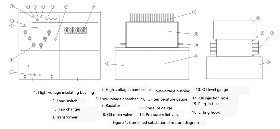
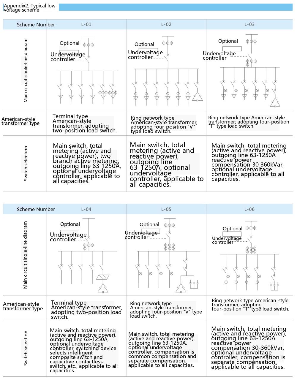
The enclosure structure of this product consists of three parts: high-voltage compartment, low-voltage compartment, and oil tank compartment. The high-voltage compartment includes high-voltage cable accessories, load switch, no-load tap changer, plug-in fuse, pressure relief valve, oil level gauge, oil thermometer, and oil drain valve. The low-voltage compartment includes low-voltage bushings, low-voltage meters, circuit breakers, and capacitor compensation. The oil tank compartment includes transformer windings and core, radiator, and the high-voltage load switch and fuses are all inside the oil tank. According to the scheme requirements, the substation structure can be designed in a "品" (pin) shape or "目" (mu) shape, as shown in the figure below.
◆ Operation of Load Switch:
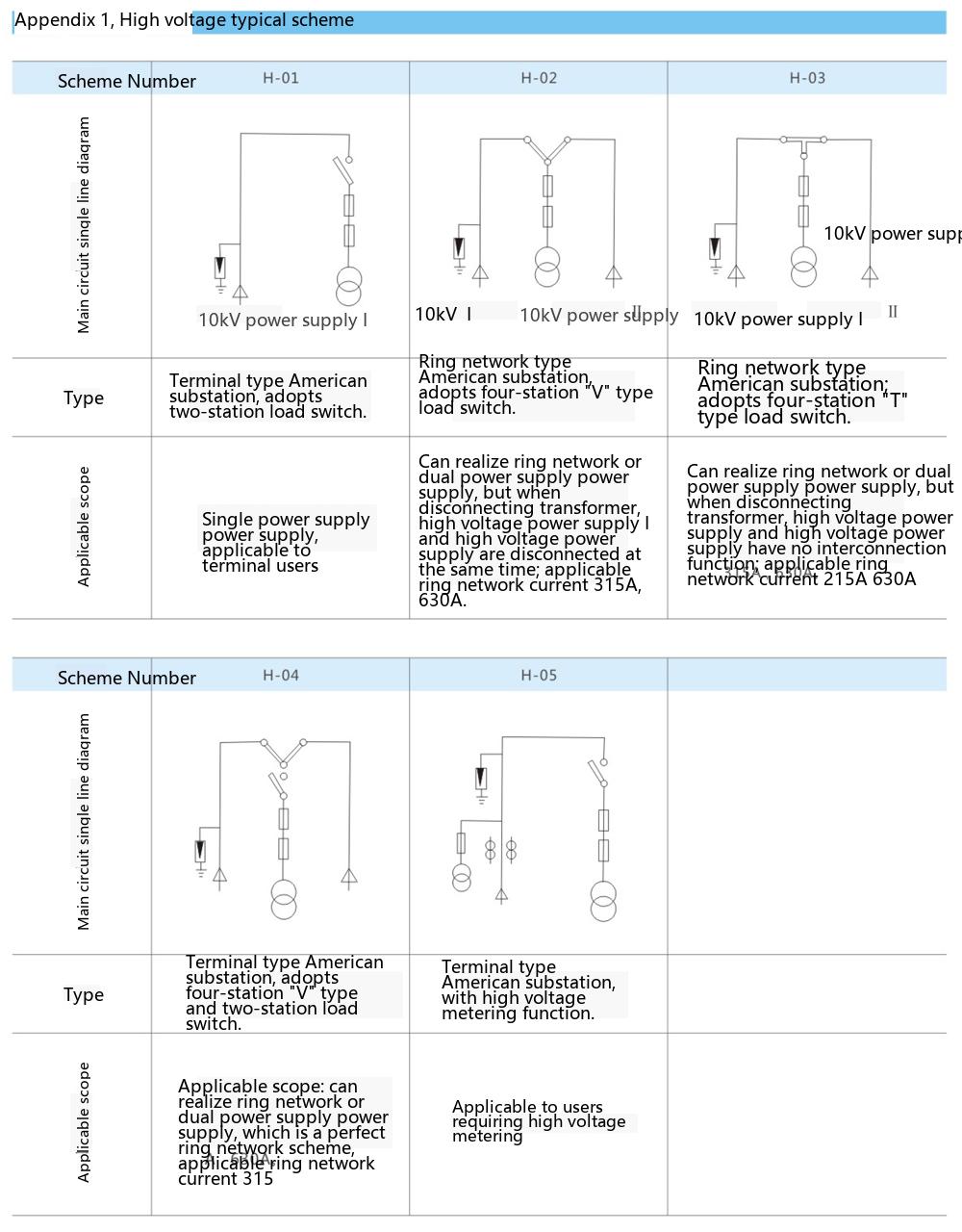
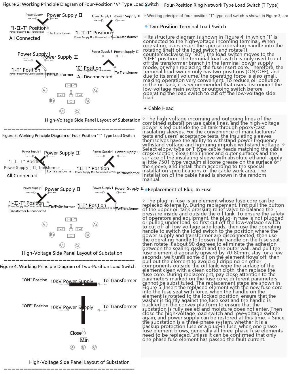
The oil-immersed load switch used in the combined substation comes in three types based on function: two-position, four-position T-type, and four-position V-type. One of these can be selected. The operations for the three types are as follows:
◇ Four-position V-type load switch refer to Figure 2. The contact structure is a "V" shape, as shown in the black part of the figure. In the figure, "I, II" are the incoming and outgoing lines for loop network power supply, and "T" is the connection to the transformer high-voltage incoming line via the backup fuse and plug-in fuse. The loop network load switch can switch the network with load.
◆ Four Operating States of the Load Switch:
◇ At the "I-II-T" position, networks "I" and "II" are connected, and the transformer is energized (the substation serves as a loop network unit);
◇ At the "I-T" position, network "I" is connected to the transformer (the substation serves as a terminal unit);
◇ At the "II-T" position, network "II" is connected to the transformer (the substation serves as a terminal unit);
◇ At the "O" position, both networks "I" and "II" are disconnected from the transformer (all are de-energized);
Insert the dedicated operating handle into the load switch shaft and rotate it approximately 130deg clockwise or counterclockwise. Each operation of the load switch moves the contact one position. Example of switch operation: switching from power supply "I" to power supply "II".
◇ Insert the dedicated operating handle into the switch shaft;
◇ Rotate the switch clockwise once. At this time, the "V" shaped blade is at the "I-II-T" position;
◇ Rotate clockwise once more. At this time, the "V" shaped blade is between "I-T", and power supply "II" is supplying power; operation complete.
◆ Operation Method 2:
◇ Insert the dedicated operating handle into the switch shaft;
◇ Rotate the switch counterclockwise once. At this time, the "V" shaped blade is at the "O" position;
◇ Rotate counterclockwise once more. At this time, the "V" shaped blade is between "II-T", and power supply "II" is supplying power; operation complete.
Both methods can be used to switch from power supply "I" to power supply "II", but the second method is safer and more reasonable. After power supply "I" is cut off, it will not be re-energized. Also, if power supply "II" fails, it will not cause a fault on the connection. Using method one may cause dual power supply, and if the phases of power supply "I" and "II" differ, it may cause a fault during the switchover.
◆ Transportation
◇ The substation should be filled with 25# (or 45#) transformer oil according to the oil level gauge指示 when leaving the factory. During transportation and handling, do not invert or turn over, avoid hitting components, and avoid strong vibrations.
◇ Special care should be taken during lifting and relocation of the substation. The lifting hooks should be attached to the lifting lugs on the oil tank. Lift slowly to prevent the wire rope from damaging the surface paint of the substation, or even causing the center of gravity to shift, tilt, or fall.
◆ Installation
◇ During on-site installation, care should be taken to protect the surface paint of the enclosure. Do not allow collisions or cracks on the pressure gauge, oil level gauge, thermometer, plug-in fuse handle, or insulating bushing components. Screws should not be loose.
◇ Clean dust and dirt from the exterior of the substation, inside the cabinet doors, and on the surfaces of insulating bushings.
◇ Check whether the nameplate data and product certificate of the substation match the purchase order, and check the documents and spare parts against the packing list.
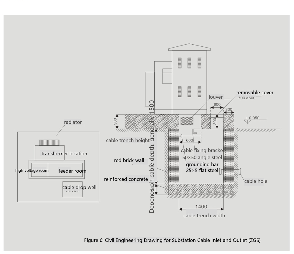
◇ The civil works drawing for cable entry and exit of the substation is shown in Figure 6.
◆ Maintenance
◇ The product has undergone strict assembly and adjustment before leaving the factory. No disassembly is required during installation to avoid affecting performance. Maintenance is limited to the following situations:
◇ Conduct transformer oil sampling analysis once a year;
◇ If the oil level is found to be low, top up promptly. The oil grade should be the same as that in the tank;
◇ After the fuse operates, the cause should be investigated. When replacing the fuse link, pay attention that its specifications and model should be the same as the original.
◇ After unpacking, check whether the documents and accessories are complete;
◇ Whether the oil level indicated by the oil level gauge complies with product specifications; whether the tap changer is in the correct position;
◇ Operate the load switch clockwise and counterclockwise, four times each. There should be no abnormal phenomena such as "failure to open or close";
◇ Measurement of DC resistance on high and low voltage sides;
◇ Measurement of transformer turns ratio;
◇ Measurement of insulation resistance and power frequency withstand voltage test (at 80% of factory test value).
The manufacturer should provide the following documents and accessories upon delivery:
◇ Delivery list
◇ Product certificate and factory test report
◇ Instruction manual
◇ Relevant electrical drawings
◇ Instructions for main components
◇ Cabinet door keys, operating handles, and spare parts specified in the contract.
When ordering, please provide our company with the following information:
◇ Product model and quantity;
◇ Transformer model and capacity;
◇ Transformer oil (25#, 45#, high flash point oil);
◇ High and low voltage side single-line wiring schemes and main component parameters;
◇ Cross-section of high-voltage incoming cable;
◇ Required spare parts.
◇ Refer to the actual dimensions of the combined substation for relevant dimensions;
◇ The concrete foundation should have a level surface. The combined substation should be fixed to the foundation using the clamping plate method;
◇ The form of the grounding busbar and cable fixing bracket can be determined according to the actual situation;
◇ The cable fixing bracket and grounding busbar should be embedded;
◇ The position of the cable entry and exit holes should be determined according to the specific situation;
◇ After installation of the combined substation, there must be a clearance of not less than 1.5m in front of the switch for operation;
◇ The grounding grid can be made of 12 galvanized round steel or 40×4 galvanized flat copper. The grounding resistance should comply with the requirements of the power department.
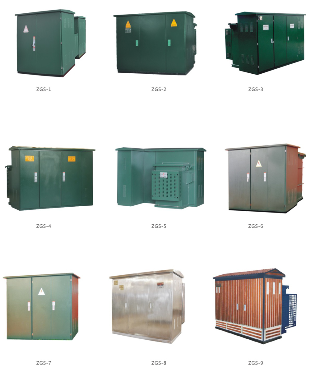
ZGS-12 Combined American-Type Substation American-Type Compact Substation 10kV Prefabricated Substation

Telephone

Online Service

Follow Us


TikTok

Back to Top


