
High Voltage Complete Switchgear Cabinet
Product Title
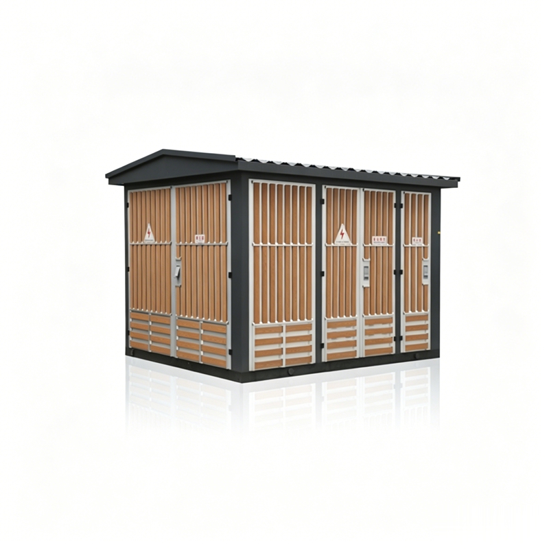
Product Details
Widely used in urban power grid renovation, residential communities, high-rise buildings, industrial and mining enterprises, hotels, shopping malls, airports, railways, oil fields, docks, highways, and temporary power facilities, both indoors and outdoors.
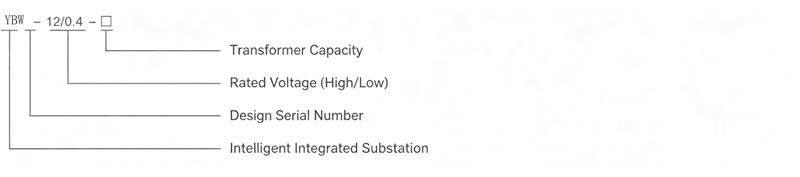
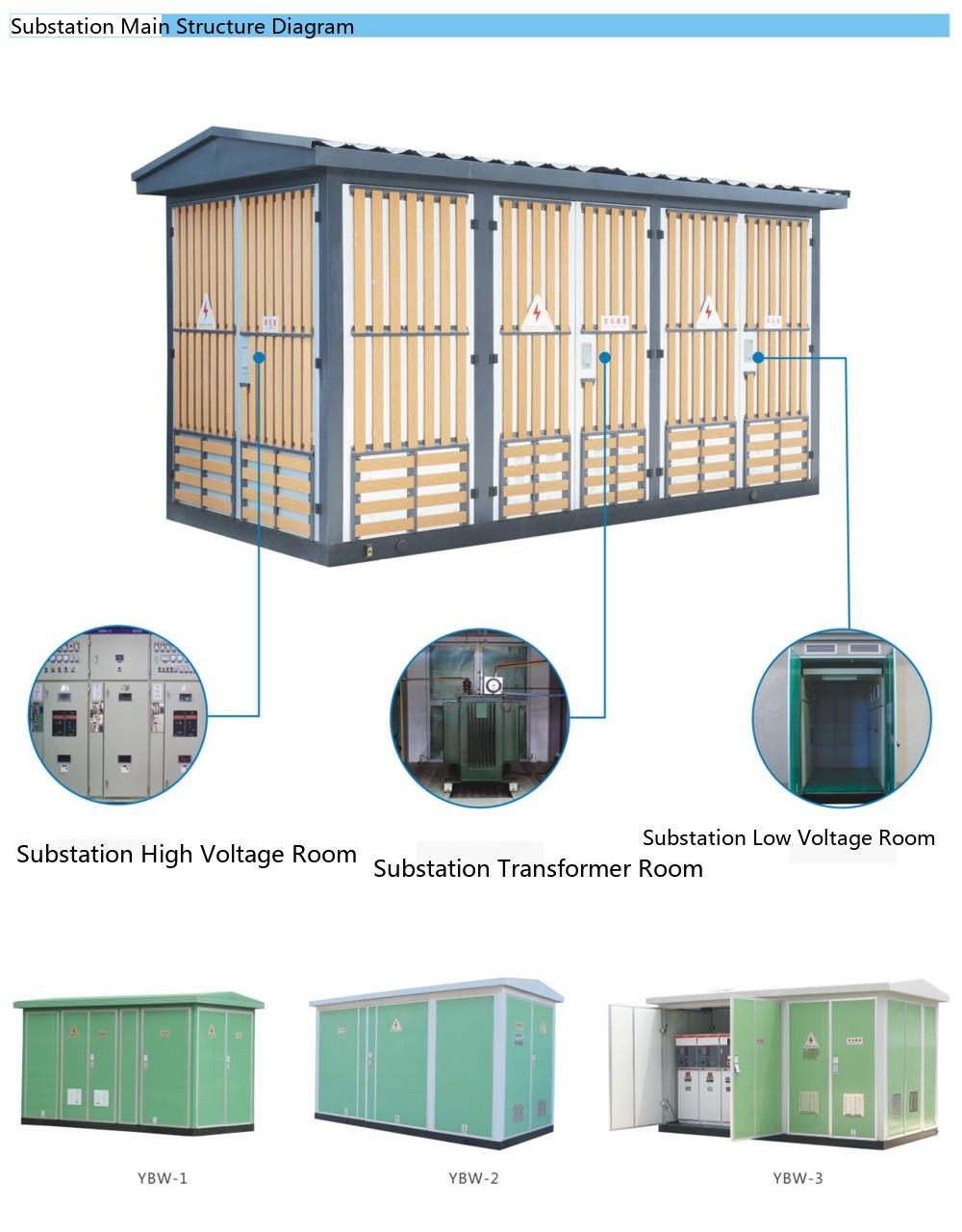
◇ Integration of high-voltage switchgear, transformer, and low-voltage switchgear in one unit, with strong system integrity;
◇ Complete high and low voltage protection, safe and reliable operation, simple maintenance;
◇ Small footprint, low investment, short production cycle, easy relocation;
◇ Flexible and diverse wiring schemes;
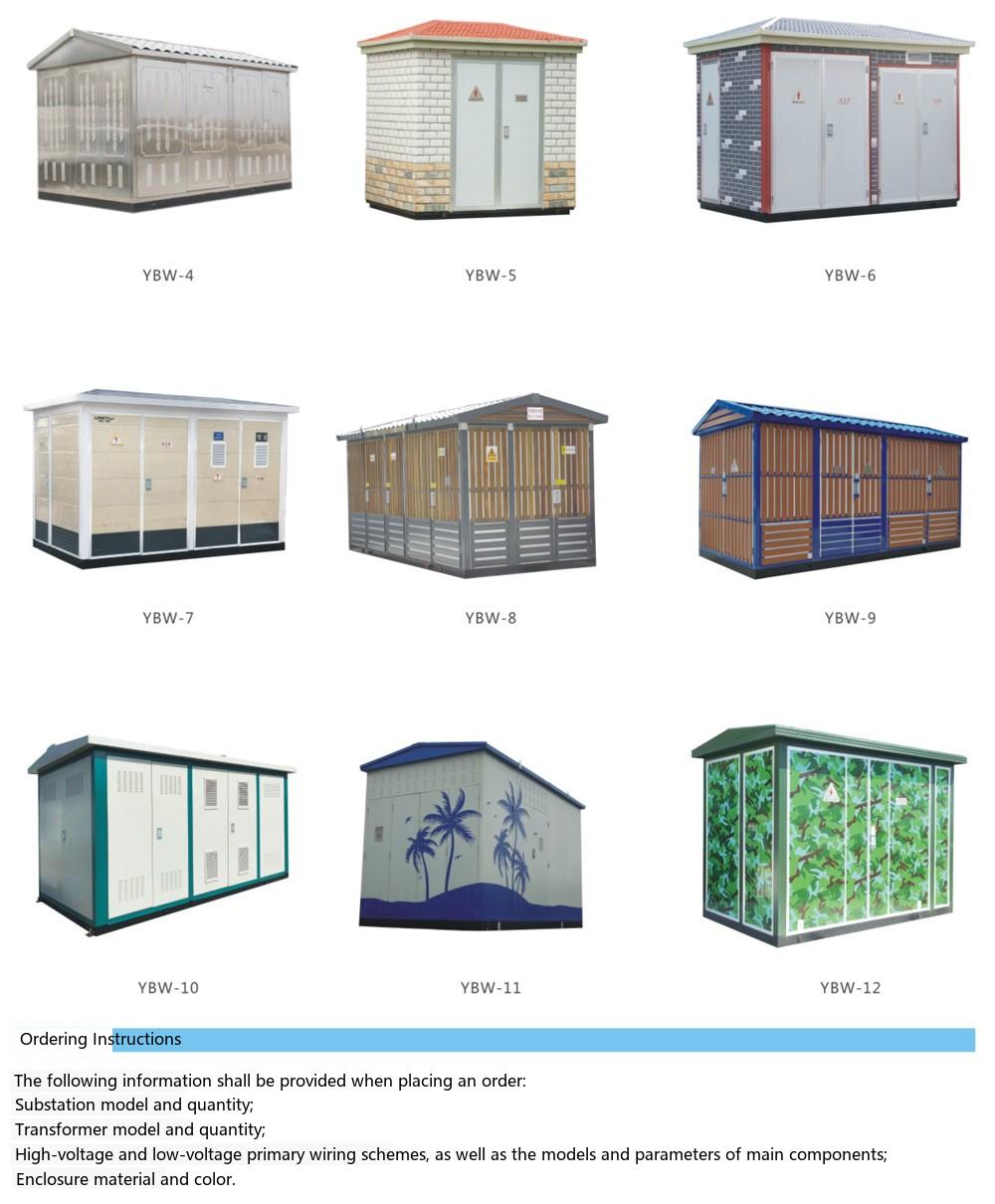
◇ Unique structure: unique honeycomb-type double-layer (composite panel) enclosure is sturdy, provides heat insulation, heat dissipation, ventilation, aesthetic appearance, and high protection level. Enclosure materials include stainless steel titanium alloy, aluminum alloy, cold-rolled steel plate, and color steel plate as options;
◇ Various types: general-purpose, villa-type, compact-type, and other styles;
◇ The high-voltage ring main unit can be equipped with a distribution network automation terminal (FTU) to achieve reliable detection of short-circuit and single-phase ground faults, with "four remote" functions to facilitate distribution network automation upgrades.
◇ Altitude: ≤1000m;
◇ Ambient temperature: -25C~+40C;
◇ Relative humidity: daily average not more than 95%, monthly average not more than 90%;
◇ Installation site free from severe shock, heavy pollution, chemical corrosion, conductive dust, and explosion hazards. If the normal operating conditions cannot be met, please consult our company for a solution.
The intelligent integrated substation uses low-loss, oil-immersed, fully sealed S9, S10, S11 series transformers, or resin-insulated or NOMEX paper-insulated environmentally friendly dry-type transformers. The transformer can be easily moved in and out.
The high-voltage side of the intelligent integrated substation generally uses a load switch-fuse combination unit for protection. After one phase of the fuse operates, a three-phase linked trip is triggered. The load switch is available in air-pressure, vacuum, and SF6 types, and can be equipped with an electric operating mechanism for automation upgrades. The fuse is a high-voltage current-limiting fuse with a striker, featuring reliable operation and large breaking capacity. For transformers above 800kVA, ZN12, ZN28, VS1 and other vacuum circuit breakers can be selected for protection.
The main switch on the low-voltage side uses a universal or intelligent circuit breaker for selective protection. The outgoing switches use new molded case switches featuring small size, short arc, and flexible outgoing configurations. An intelligent automatic tracking reactive power compensation device is available, with both contactor and contactless switching methods for user selection.
GB/T 17467-1998 "High-voltage/Low-voltage Prefabricated Substations"
DL/T 537-93 "Technical Conditions for Ordering 6-35kV Compact Substations"
| Item Name | FN12-12 Load Switch | FZN25-12 Vacuum Load Switch | ||
| 1 | Rated Voltage | kV | 10 | 10 |
| 2 | Operating Voltage | kV | 12 | 12 |
| 3 | Rated Frequency | Hz | 50 | 50 |
| 4 | Rated Current | A | 630 | 630 |
| 5 | Rated Load Current Breaking Capacity | A | 630 | 630 |
| 6 | Thermal Stability Current | kA/S | 20/2 | 20/4 |
| 7 | Dynamic Stability Current | kA | 50 | 50 |
| 8 | Short-circuit Making Current | kA | 50 | 50 |
| 9 | Full Load Breaking Operations | times | 20 | 10000 |
| 10 | Mechanical Life | times | 2000 | 10000 |
| 11 | 1min Power Frequency Withstand Voltage | kV | 42 | 42 |
| 12 | Lightning Impulse Withstand Voltage | kV | 75 | 75 |
| Model | Rated Voltage (kV) | Breaking Current (A) | Breaking Current (kA) | Fuse Element Rated Current (A) | |
| SDL※J | 12 | 40 | 31.5 | 6,3,10,16,20,25,31.5,40 | |
| SFL※J | XRNT-12 | 12 | 100 | 31.5 | 50,63,71,80,100 |
| SKL※J | 12 | 125 | 31.5 | 125 | |
| Model | Trip Unit Type | Trip Unit Rated Current A | Breaking Capacity kA (AC380V) |
| DW15-630 | Thermal-Magnetic or Electronic Type |
315,400,630 | 40 |
| DW15-1000 | 630,800,1000 | 50 | |
| DW15-1600 | 1600 | 50 | |
| DW15-2500 | 1600,2000,2500 | 60 | |
| CW1-2000 | Intelligent Type | 630,800,1000,1250,1600,2000 | 65(80) |
| CW1-3200 | 2000,2500,3200 | 100 |
Note: (80) indicates high breaking capacity type.
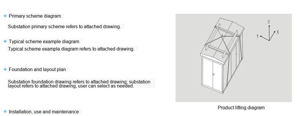
In addition to the various regulations required by the power department for installation, acceptance, commissioning tests, operation, and maintenance of the intelligent integrated substation, please note the following:
◇ Upon receipt, the user should inspect carefully according to relevant regulations. Products not installed immediately should be stored in a suitable place according to normal operating conditions.
◇ The product should be lifted from the bottom using dedicated lifting equipment, as shown in the right figure.
◇ The product should be placed horizontally on a pre-made foundation, and the gap between the product base and the foundation should be sealed with cement mortar to prevent rainwater from entering the cable compartment. High and low voltage cables should be connected through the bottom sealing plate of the high and low voltage compartments.
◇ After installation, the product should be reliably grounded. The two main grounding terminals on the base channel steel, the transformer neutral point and enclosure, and the lower terminals of the arrester should all be grounded by the installation department.
All grounding should share one set of grounding devices, with a grounding resistance of less than 4 ohms. At least two grounding leads should be run from the grounding grid to the product.
◆ Before commissioning after installation or maintenance, the following inspections and tests should be carried out:
◇ Cleanliness inside the substation;
◇ Flexibility of the operating mechanism;
◇ Reliable making and breaking of main electrical apparatus;
◇ Reliable and accurate making and breaking of auxiliary contacts;
◇ Accuracy of meters and relay operations;
◇ Correctness of instrument and transformer ratios and wiring polarity;
◇ Tightness and secure installation of all electrical apparatus mounting nuts;
◇ Good busbar connections and reliable installation of supporting insulators and clamps;
◇ Compliance of electrical apparatus settings and correctness of fuse link specifications;
◇ Compliance of main and auxiliary circuit connections with the electrical schematic diagram.
◆ Maintenance
◇ All components in the product should be maintained according to their respective technical requirements;
◇ If an oil-immersed transformer is selected, an oil sample analysis should be conducted at least once a year as required;
◇ After 20 load operations or 2000 no-load opening/closing operations of the high-voltage switchgear on the operating side, the contact condition and arc extinguishing device wear should be checked. If abnormalities are found, repair or replacement should be carried out promptly.
◇ After automatic tripping of the low-voltage switchgear, the cause of tripping should be analyzed and the fault cleared before re-commissioning;
◇ Lightning arresters should be subjected to a preventive test before the thunderstorm season each year.
Note: The product is accompanied by a packing list, certificate of conformity, installation and operation manual, electrical wiring diagram, instruction manuals for the main component equipment used in the product, key operating tools, and spare parts provided according to the agreement.
Technical Scheme Diagram Examples
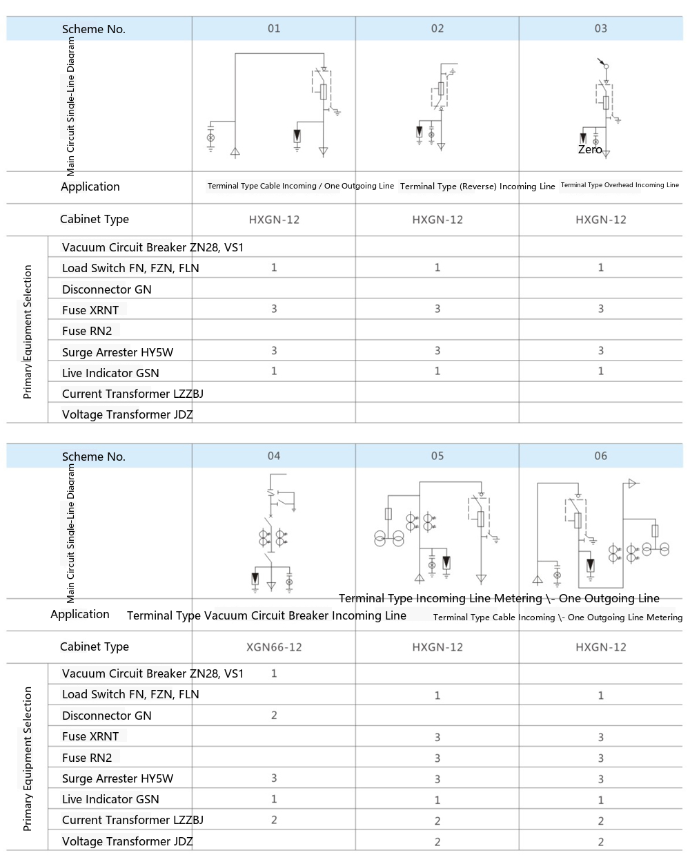
YBW-12 Prefabricated Substation European-Type Substation 10kV Outdoor Compact Substation

Telephone

Online Service

Follow Us


TikTok

Back to Top


