
High Voltage Complete Switchgear Cabinet
Product Title
Product Details
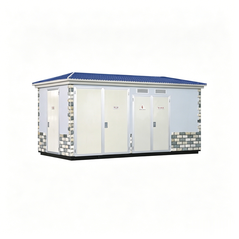
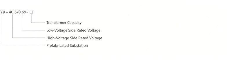
The YB-40.5 wind power generation compact substation (hereinafter referred to as the compact substation) is a dedicated device that steps up the voltage from 0.6~0.69kV generated by wind turbines to 35kV for grid connection output. This product is a new development by our company in response to the requirements of large single-unit capacity and high protection levels in offshore wind farms.
◇ Altitude not exceeding 1000m;
◇ Ambient temperature: -45C~+45C;
◇ Relative humidity: daily average less than 95%, monthly average less than 90%;
◇ Installation site: free from fire, explosion hazards, conductive dust, chemically corrosive gases, and severe vibration. If the conditions exceed the above, the user can consult with our company.
◇ Integration of high-voltage switchgear, transformer, and low-voltage switchgear in one unit, with strong system integrity; low loss, low noise, excellent performance, and the enclosure adopts an anti-theft structure;
◇ Complete high and low voltage protection, safe and reliable operation, simple maintenance; flexible and diverse wiring schemes;
◇ The high-voltage side generally uses a load switch-fuse combination unit for protection. After one phase of the fuse operates, a three-phase linked trip is triggered. The load switch is available in vacuum, SF6, and other types, and can be equipped with an electric operating mechanism for automation upgrades. The fuse is a high-voltage current-limiting fuse with a striker, featuring reliable operation and large breaking capacity. The main technical parameters are shown in the table below. The vacuum load switch is recommended for the high-voltage load switch product. The spring operating mechanism uses AC220V operation, equipped with a compact substation protection device and light and heavy gas interfaces. Fuses are matched according to transformer capacity, and arresters and live display devices are included. The vacuum interrupter chamber, disconnector, and earthing switch of the combination unit have reliable mechanical interlocking. The disconnector and earthing switch can only be operated when the vacuum interrupter chamber is in the open position. The disconnector and earthing switch are interlocked. The tripping mechanism of the fuse is three-pole linked, and the fuse used is a striker-type fuse. The striker can directly trip the load switch, ensuring rapid fault clearance.
◇ The main switch on the low-voltage side uses a universal or intelligent circuit breaker for selective protection.
◇ Uses low-loss, oil-immersed, fully sealed S9, S10, S11 series transformers. Resin-insulated or paper-insulated environmentally friendly dry-type transformers are also available. Each is equipped with a trolley at the bottom, allowing the transformer to be easily moved in and out.
◇ The enclosure material uses a non-metallic environmentally friendly enclosure, which is corrosion-resistant and salt-fog resistant. Composite panels, stainless steel plates, etc., can also be selected.
◇ The compact substation can be equipped with an operating corridor on the high and low voltage sides according to user requirements.
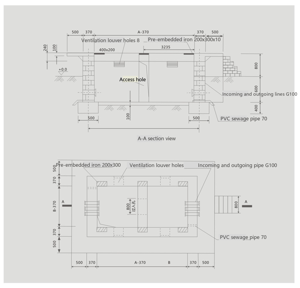
◇ The number and orientation of embedded cable conduits in the foundation should be determined by the user based on the number and orientation of cables;
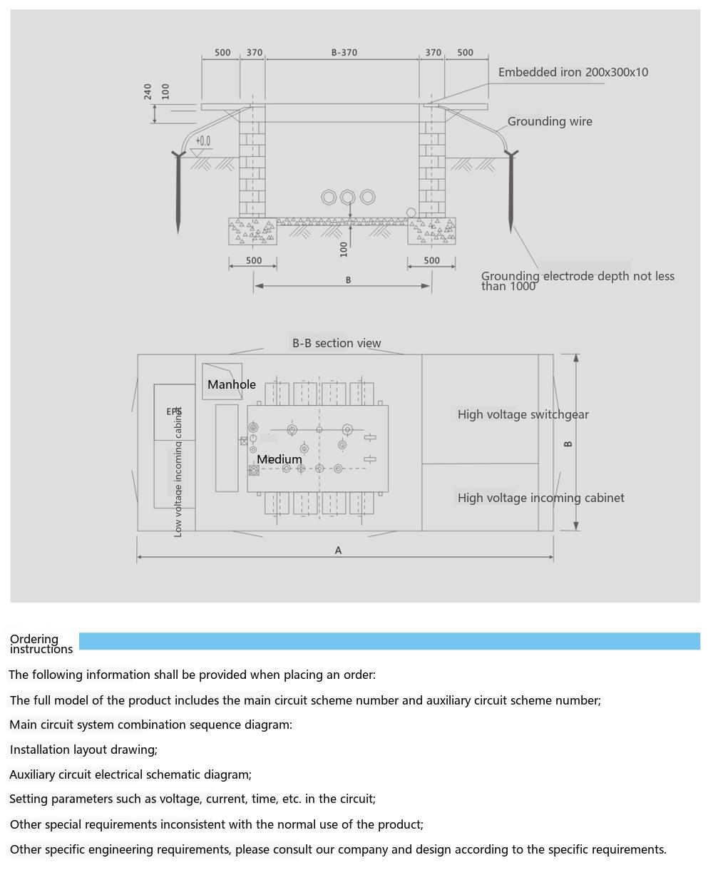
◇ All embedded iron parts and supports in the foundation should be grounded;
◇ The number of grounding rods is determined by the soil conditions. It is essential to ensure the grounding resistance is less than 4Ω;
◇ The grounding conductor can be made of 40×4 galvanized flat steel, and the grounding electrode can be made of 5# angle steel;
◇ The connection between the grounding electrode and the grounding conductor should be welded and coated with asphalt for anti-corrosion.
The following information should be provided when ordering:
◇ The full model of the product, including the main circuit scheme number and auxiliary circuit scheme number;
◇ The combination sequence diagram of the main circuit system;
◇ The installation layout plan;
◇ The electrical schematic diagram of the auxiliary circuit;
◇ The setting parameters for voltage, current, time, etc., in the circuit;
◇ Other special requirements that do not conform to the normal use of the product;
◇ For other specific engineering requirements, please consult with our company for design according to specific requirements.
YB-40.5KV Wind Power Generation Compact Substation 35KV Compact Substation Wind Power Dedicated Compact Substation

Telephone

Online Service

Follow Us


TikTok

Back to Top


