
High Voltage Complete Switchgear Cabinet
Product Title
Product Details
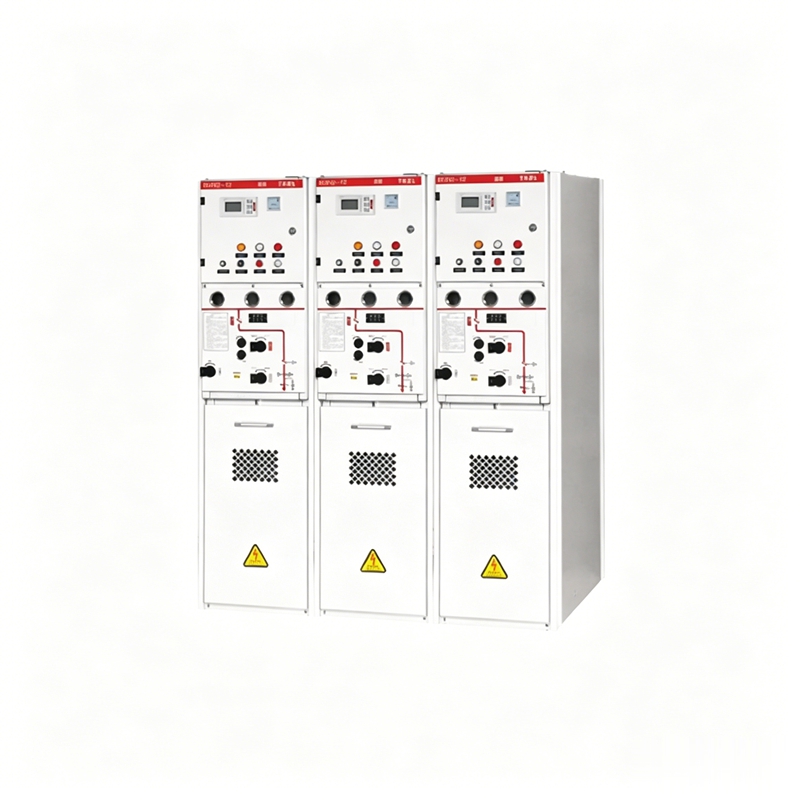
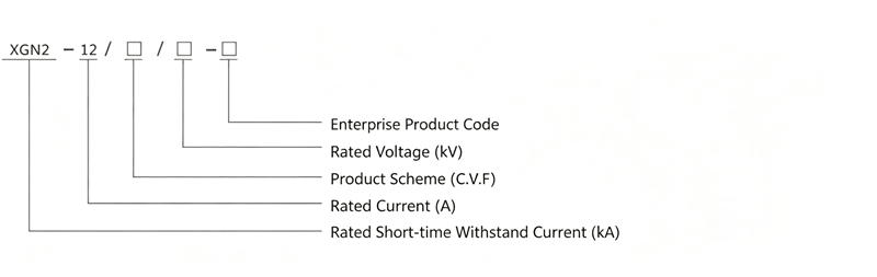
The XGN2-12 solid insulated ring main unit is an environmentally friendly composite insulated ring main unit independently developed by our company. It is a fully sealed power supply unit. All live parts and switches are fully sealed within an epoxy resin housing, with no SF6 gas inside the housing. The entire switchgear is unaffected by the external environment, ensuring operational reliability and personal safety, and achieving maintenance-free operation.
The solid insulated ring main unit consists of three types of switches: V unit (circuit breaker unit), C unit (load switch unit), and F unit (combination unit). Each unit can be used independently or freely expanded. Its structure is divided into the intelligent control instrument room, operating mechanism, and primary part. The instrument room can be equipped with a microcomputer protection device (controller). The primary part uses the APG automatic gelation process to completely encapsulate the disconnector and arc extinguishing chamber in epoxy resin, with dedicated connectors connected to the busbar. The arc extinguishing chamber uses dedicated copper-chromium contact material, R-type transverse magnetic field contacts, and a complete one-time sealing and exhaust process. This arc extinguishing chamber has significantly improved short-circuit current breaking capacity and stability, electrical life, temperature rise, and insulation level compared to previous arc extinguishing chambers (copper-aluminum contact material, cup-shaped transverse magnetic field contact structure, and incomplete one-time sealing and exhaust process). The operating mechanism uses a spring mechanism integrated with the switch, meaning the disconnector and main switch spring mechanism are one unit, easily achieving interlocking. The mechanism has fewer parts, reducing unnecessary transmission links and enhancing reliability. Electric operation can also be achieved according to user needs.
Solid insulated ring main unit: uses solid insulating material as the main insulation medium and encapsulates the main conductive circuits such as conductive connections, disconnectors, earthing switches, main busbar, and branch busbars, either individually or in combination, with solid insulation material to form one or several modules with certain functions, which can be recombined or expanded, featuring fully insulated and fully sealed performance.
The ring main unit is suitable for 12kV, 50Hz three-phase AC distribution systems, used for loop network or terminal power supply. The ring main unit can be installed in distribution systems of industrial and mining enterprises, residential communities, schools, parks, etc., and can also be installed in compact compact substations for control and protection of distribution transformers. Both indoor and outdoor ring main units can achieve distribution automation.
◇ Suitable for indoor or outdoor use.
◇ Ambient air temperature: indoor -10C~+25C, outdoor -60C~+60C.
◇ Air relative humidity: daily average not more than 95%, monthly average not more than 90%.
◇ Altitude not more than 3000m.
◇ Ambient air should not be significantly contaminated by dust, water vapor, salt fog, corrosive gases, or flammable gases; outdoor models can be used in more severe environmental conditions.
◇ Installation site free from severe vibration, earthquake intensity not exceeding 8 degrees.
◇ If the above environmental conditions cannot be met, the user should consult with the manufacturer.
◇ IEC62271-1-2007 "High-voltage Switchgear and Controlgear - Part 1: Common Specifications"
◇ IEC620071-200-2003 "1~52KV AC Metal-enclosed Switchgear and Controlgear"
◇ GB3906-2006 "3.6~40.5KV AC Metal-enclosed Switchgear and Controlgear"
◇ GB/T11022-2011 "Common Technical Conditions for High-voltage Switchgear and Controlgear Standards"
◇ GB1984-2014 "High-voltage AC Circuit Breakers"
◇ GB1985-2014 "High-voltage AC Disconnectors and Earthing Switches"
◇ GB3804-2004 "3.6KV~40.5KV High-voltage AC Load Switches"
◇ DL/T404-2007 "3.6KV~40.5KV AC Metal-enclosed Switchgear and Controlgear"
◇ DL/T593-2016 "Common Technical Conditions for High-voltage Switchgear and Controlgear Standards"
◇ Q/GDW730-2012 "Technical Conditions for 12KV Solid Insulated Ring Main Units"
◇ DL/T402-2016 "High-voltage AC Circuit Breakers"
◇ Overall Technical Parameters of Switchgear Table
| No. | Name | Unit | Parameter |
|---|---|---|---|
| 1 | Rated Voltage | kV | 12 |
| 2 | Rated Current | A | 630 |
| 3 | Rated Short-time Withstand Current (4s) | kA | 25 |
| 4 | Rated Peak Withstand Current | kA | 50 |
| 5 | Rated Short-circuit Making Current (Peak) | kA | 50 |
| 6 | Rated Active Load Breaking Current | A | 630 |
| 7 | Rated Closed-loop Breaking Current | A | 630 |
| 8 | Rated Cable Charging Breaking Current | A | 10 |
| 9 | Rated Transfer Current of Combination Unit | A | 3700 |
| 10 | 1min Power Frequency Withstand Voltage | kV | Phase-phase/earth, Vacuum gap 42 |
| Isolating gap 48 | |||
| 11 | Lightning Impulse Withstand Voltage | kV | Phase-phase/earth, Vacuum gap 75 |
| Isolating gap 85 | |||
| 12 | Mechanical Life | times | Circuit breaker 10000 |
| Disconnector, Earthing switch 3000 | |||
| 13 | Protection Level | IP4X | |
| 14 | Enclosure Protection Level | IP4X | |
| 15 | Circuit Breaker Partial Discharge | PC | ≤20 (measured at 1.2Ur) |
◇ Rated Parameters of Circuit Breaker Unit Table
| No. | Name | Unit | Parameter |
|---|---|---|---|
| 1 | Rated Voltage | kV | 12 |
| 2 | Rated Current | A | 630 |
| 3 | Rated Cable Charging Breaking Current | A | 10 |
| 4 | Rated Short-time Withstand Current (4S) | kA | 25 |
| 5 | Rated Peak Withstand Current | kA | 50 |
| 6 | Rated Short-circuit Breaking Current | kA | 25 |
| 7 | Contact Gap | mm | 9±1 |
| 8 | Over-travel | mm | 3.0±0.5 |
| 9 | Phase-to-Phase Center Distance | mm | 130±1.5 |
| 10 | Main Circuit Resistance | μΩ | ≤350 |
| 11 | Closing Time | ms | 25~60 |
| 12 | Opening Time | ms | 17~45 |
| 13 | 1min Power Frequency Withstand Voltage | kV | Phase-phase/earth, Vacuum gap 42 |
| Isolating gap 48 | |||
| 14 | Lightning Impulse Withstand Voltage | kV | Phase-phase/earth, Vacuum gap 75 |
| Isolating gap 85 | |||
| 15 | Mechanical Life | times | Circuit breaker 10000 |
| Disconnector, Earthing switch 3000 | |||
| 16 | Circuit Breaker | m/s | Average closing speed 0.9±0.2 |
| m/s | Average opening speed 1.3±0.2 | ||
| ms | Three-phase synchronism ≤2 | ||
| 17 | Partial Discharge | PC | ≤20 (measured at 1.2Ur) |
◇ Rated Parameters of Load Switch Unit Table
| No. | Name | Unit | Parameter |
|---|---|---|---|
| 1 | Rated Voltage | kV | 12 |
| 2 | Rated Current | A | 630 |
| 3 | Rated Short-time Withstand Current (4S) | kA | 25 |
| 4 | Rated Peak Withstand Current | kA | 50 |
| 5 | Rated Short-circuit Making Current (Peak) (E2) | kA | 50 (3 times) |
| 6 | Rated Active Load Breaking Current | A | 630 |
| 7 | Rated Earth Fault Breaking Current | A | 30 |
| 8 | Rated Cable Charging Breaking Current | A | 10 |
| 9 | Rated Closed-loop Breaking Current | A | 630 |
| 10 | Contact Gap | mm | 9±1 |
| 11 | Over-travel | mm | 3.0±0.5 |
| 12 | Phase-to-Phase Center Distance | mm | 130±1.5 |
| 13 | Main Circuit Resistance | μΩ | ≤350 |
| 14 | Closing Time (including energy storage time) | s | ≤10 |
| 15 | Opening Time | ms | 17~45 |
| 16 | 1min Power Frequency Withstand Voltage | kV | Phase-phase/earth, Vacuum gap 42 |
| Isolating gap 48 | |||
| 17 | Lightning Impulse Withstand Voltage | kV | Phase-phase/earth, Vacuum gap 75 |
| Isolating gap 85 | |||
| 18 | Mechanical Life | times | Load switch 10000 |
| Disconnector, Earthing switch 3000 | |||
| 19 | Load Switch | m/s | Average closing speed 0.9±0.2 |
| m/s | Average opening speed 1.3±0.2 | ||
| ms | Three-phase synchronism ≤2 | ||
| 20 | Partial Discharge | PC | ≤20 (measured at 1.2Ur) |
◇ Rated Parameters of Combination Unit Table
| No. | Name | Unit | Parameter |
|---|---|---|---|
| 1 | Rated Voltage | kV | 12 |
| 2 | Rated Current | A | 630 |
| 3 | Rated Frequency | Hz | 50 |
| 4 | Rated Short-circuit Breaking Current | kA | 31.5 |
| 5 | Rated Transfer Current of Combination Unit | A | 3700 |
| 6 | Main Circuit Resistance (excluding fuse) | μΩ | ≤750 |
| 7 | 1min Power Frequency Withstand Voltage | kV | Phase-phase/earth, Vacuum gap 42 |
| Isolating gap 48 | |||
| 8 | Lightning Impulse Withstand Voltage | kV | Phase-phase/earth, Vacuum gap 75 |
| Isolating gap 85 | |||
| 9 | Mechanical Life | times | Circuit breaker, Earthing switch 10000 |
| Load switch 3000 | |||
| 10 | Auxiliary Circuit 1min Power Frequency Withstand Voltage (voltage >110V) | kV | 2.5 |
| 11 | Partial Discharge | PC | ≤20 (measured at 1.2Ur) |
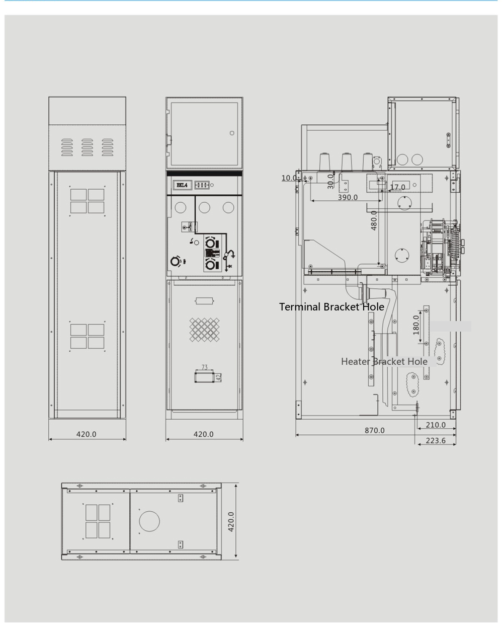
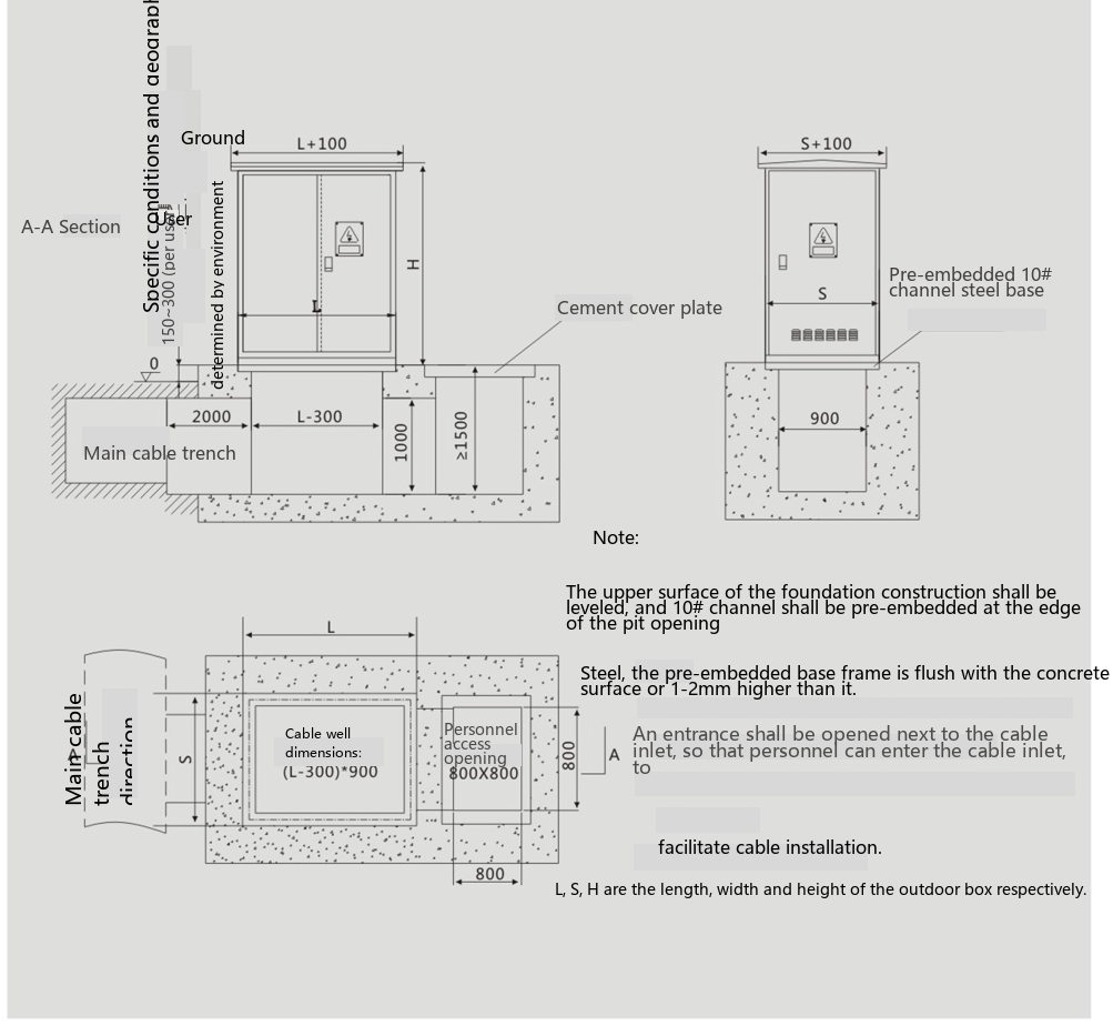
The ring main unit should be installed in a well-ventilated place, with operation and maintenance carried out from the front. The base of the ring main unit has anchor bolt mounting holes. Indoor cabinets can be installed away from or against the wall. The installation position is shown in the figure. The flatness of the rails laid on the installation foundation should not exceed 2mm per square meter. The base of the ring main unit must be fixed to the foundation. For outdoor installation, the foundation should be built on higher ground, and the distance from surrounding walls or obstructions should not be less than 1 meter to avoid hindering door opening. The pit wall should be built with cement and solid bricks, and the surface should be treated for waterproofing. The pit wall and foundation platform should be finished with a 1:2.5 cement mortar layer with a thickness of 20mm, and the surface must be level. Concrete construction should comply with GB232-82 "Code for Construction and Acceptance of Electrical Installation Works". After cable installation, the cable compartment floor should be sealed to prevent moisture from the trench from entering. The connection of the ring main unit must be connected to the on-site grounding grid. The grounding point of the ring main unit has a grounding mark.
The packaged ring main unit can be handled with an electric forklift or crane. The ring main unit is equipped with lifting rings for lifting during handling. Lifting ropes should not be shorter than 2m.
Before installation at the usage site, the ring main unit should be stored in a dry, ventilated, dust-free place. If covered with plastic bags, the bottom should be left open for ventilation.
◆ Pre-Operation Inspection: Before using the ring main unit, the following inspections must be carried out for personnel and equipment safety
◇ Check whether the main circuit and grounding circuit are correctly connected.
◇ Check whether the mechanical interlocking is correct and reliable.
◇ Check whether the operation of the load switch and earthing switch in the ring main unit is flexible and correct.
◇ Check whether the connection of the high-voltage cables is correct and reliable.
◆ Operation
◇ The ring main unit should be put into operation according to the specified operating sequence.
◇ All live parts are installed in epoxy resin insulating tubes.
◇ All operating mechanism parts placed outside the epoxy resin insulating tubes have been electroplated.
◇ The main shaft is supported by copper sleeves and can work continuously and effectively even without lubrication.
◇ Note: If the ring main unit has a fault, do not attempt to open the ring main unit for repair using drills, cutting tools, or other tools. These operations should only be carried out by our company's personnel.
The following documents and accessories are supplied with the product:
◇ Product installation and operation manual.
◇ Product factory test report.
◇ Product certificate of conformity.
◇ Packing list.
◇ Operating handle.
◇ Other accessories.
XGN2-12 Solid Insulated Ring Main Unit 10kV/630A Environmentally Friendly Ring Main Unit SF6-Free Fully Sealed Switchgear

Telephone

Online Service

Follow Us


TikTok

Back to Top


