
High Voltage Complete Switchgear Cabinet
Product Title
Product Details
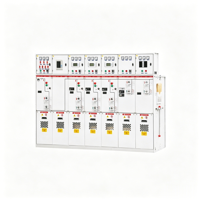
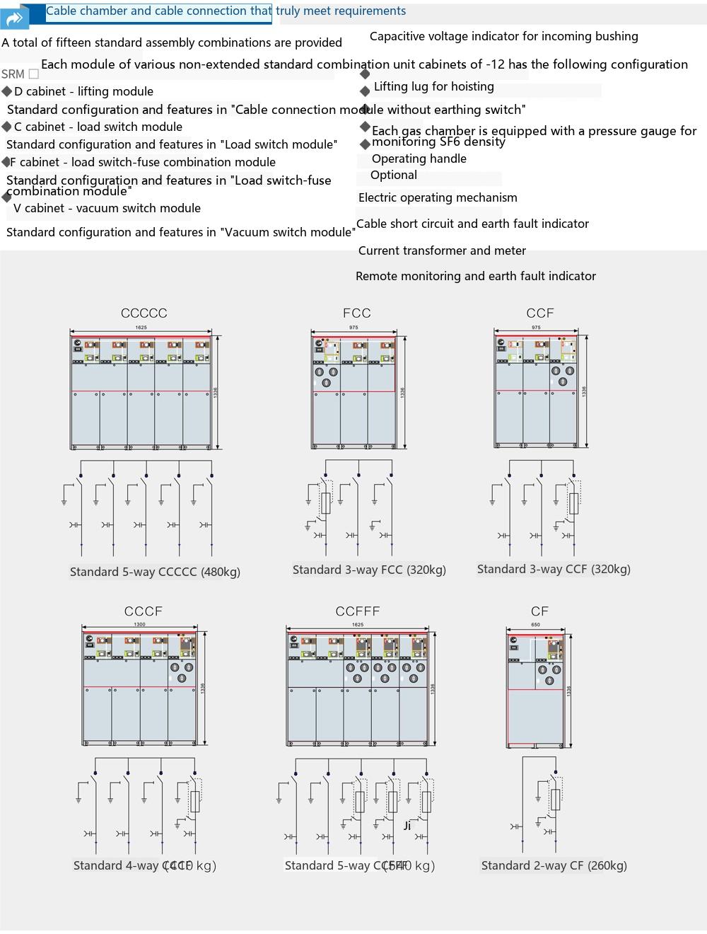
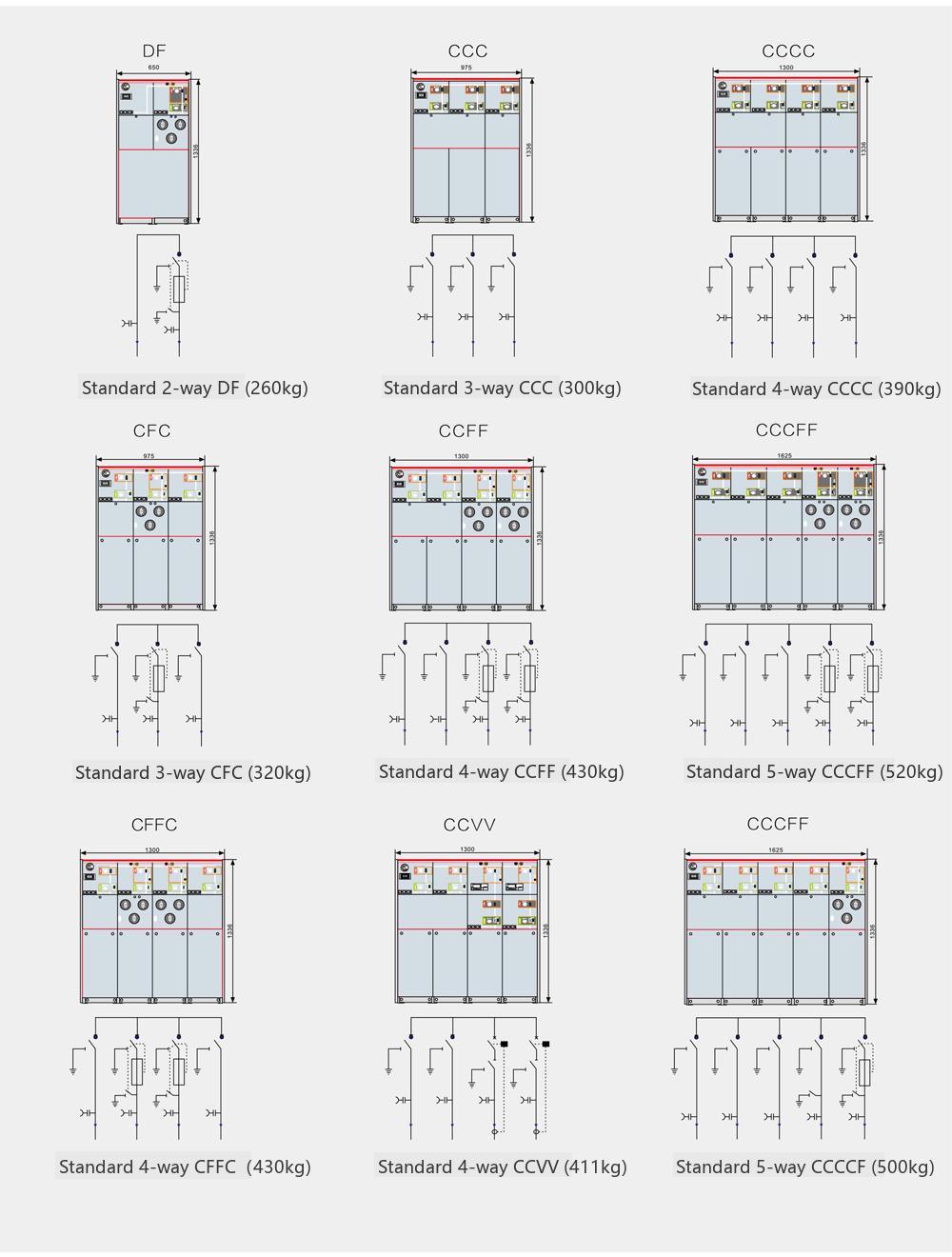
The SRM□-12 series ring main switchgear is SF6 gas-insulated metal-enclosed switchgear with a common tank. This equipment can be composed of modules such as load switch units, load switch-fuse combination units, vacuum circuit breaker units, and busbar incoming units. It adopts a series of excellent technologies and materials, offering excellent electrical and mechanical properties, minimal impact from environment and climate, compact size, easy installation, convenient operation, maintenance-free, and flexible combination methods. The clear and intuitive design ensures simple and direct operation. The feeder has large connection capacity, suitable for various wiring systems.
| Unit Code | Meaning |
|---|---|
| C | Standard Single Bushing Load Switch Unit |
| F | Load Switch-Fuse Combination Unit |
| V | Circuit Breaker Unit |
| D | Cable Incoming Unit (without switch) |
| + | Busbar Side Bushing |
| - | Busbar Top Bushing |
| SL | Bus Coupler Unit |
| M | Metering Unit |
| PT | PT Unit |
| 1K2(4) | Load Switch Unit with Double Bushing Outgoing |
Operational Safety:
Through the following safety measures, we can provide users with special safety guarantees:
Integrated three-position load switch
The circuit breaker uses a load switch instead of a disconnector, which is safer and more reliable. The primary side fully enclosed design provides protection against accidental contact. The mechanical interlocking meets the five-prevention requirements. The live display device provides live indication for incoming and outgoing lines. Reliable operation: Fully enclosed design, all 10kV switch and busbar live conductors are sealed in a gas tank welded from 3mm stainless steel plates. Equipped with silicone rubber cable plugs, achieving full insulation and full sealing of cable terminations, thus不受 dust, moisture, small animals, and other external environmental influences. Spring-operated mechanism, can be manually or electrically operated. The panel mimic diagram provides switch position indication. The cabinet is made of galvanized steel plates with electrostatic spraying on the surface, enhancing corrosion resistance. The pressure gauge monitors the safe pressure range of SF6 gas inside the tank.
Economy:
Maintenance-free
Highly reliable
Service life up to 20 years
Flexible Schemes:
Multiple incoming methods,可以实现 left, right, top, or front incoming
Multiple combination methods, arbitrary combinations between units
Using insulated busbars,可以实现 front-to-back or left-to-right cabinet combination
Flexible design schemes
Wide Application:
Large feeder capacity, small footprint, suitable for various application needs.
| SF6 Gas Pressure | Absolute pressure 1.4 bar at 20C | Normal Operating Environmental Conditions | |
| Gas Annual Leakage Rate | 0.2%/year | Maximum Temperature | 40C |
| Protection Level | IP67 | Minimum Temperature | -40C |
| Gas Tank Stainless Steel Thickness | 3.0mm | Maximum Average Relative Humidity | ≤ 95% |
| Altitude | ≤ 2000 meters | ||
| Busbar | Applicable Standards | ||
| Busbar inside switchgear | 400mm2Cu | GB/T11022 | GB3906 GB1985 |
| Switchgear earthing busbar | 150mm2Cu | GB16926 | GB38041 GB1984 |
| GB3309 | |||
| Color | IEC60056 | IEC60129 IEC60265 | |
| Switchgear front panel | RAL7012 | IEC60298 | IEC60420 IEC60694 |
| Side panel and cable compartment front cover | RAL7035 |
| Item | C Module Load Switch | F Module Combination Unit | V Module Vacuum Switch | Disconnector/Earthing Switch | CB Module Vacuum Circuit Breaker | Disconnector/Earthing Switch |
|---|---|---|---|---|---|---|
| Rated Voltage kV | 12 | 12 | 12 | 12 | 12 | 12 |
| Rated Frequency Hz | 50 | 50 | 50 | 50 | 50 | 50 |
| Power Frequency Withstand Voltage (Phase-to-phase/Port) kV | 42/48 | 42/48 | 42/48 | 42/48 | 42/48 | 42/48 |
| Lightning Impulse Withstand Voltage kV | 75/85 | 75/85 | 75/85 | 75/85 | 75/85 | 75/85 |
| Rated Current A | 630 | Note | 630 | 1250/630 | ||
| Rated Closed-loop Breaking Current A | 630 | |||||
| Rated Cable Charging Breaking Current A | 135/135 | |||||
| Rated Short-circuit Making Current (Peak) | 50 | 80 | ||||
| Rated Peak Withstand Current kA | 50 | |||||
| Rated Short-time Withstand Current kA/3s | 20 | |||||
| Rated Short-circuit Breaking Current kA | 31.5 | 20 | 25 | 25 | ||
| Rated Transfer Current A | 1750 | |||||
| Maximum Fuse Current Used A | - | 125 | ||||
| Circuit Resistance μΩ | ≤ 300 | ≤ 600 | ||||
| Mechanical Life (times) | 5000 | 3000 | 5000 | 2000 | 5000 | 5000 |
Note: (1) Depends on the current rating of the fuse.
The SRM□-12 gas-insulated fully insulated fully enclosed ring main switchgear is installed on a galvanized steel frame. The switch unit is inside the SF6 gas tank, which is made of corrosion-resistant and non-magnetic 3mm thick stainless steel plate. The SF6 gas tank is a "sealed pressure system" and can operate for 20 years under normal working conditions. The normal working pressure of SF6 gas is 0.015-0.04MPa. The gas tank is equipped with a pressure relief device, ensuring that gas can be released from the bottom or rear if the pressure is too high.
The load switch adopts a coaxial rotary double-break method, performing functional operations through the same operating hole and slide plate combination. Therefore, the switch can only be in one of the three states "closed, open, earthed" at any time, completely avoiding misoperation.
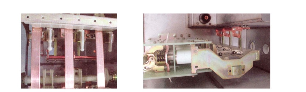


The pressure relief device is separated from the cable compartment by a metal plate. If the pressure inside the gas tank becomes too high, the explosion-proof diaphragm inside the device ruptures to release pressure.
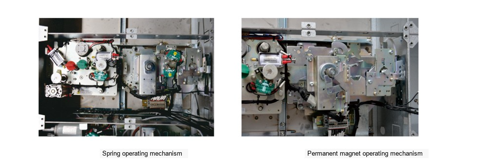
The switch operating mechanism is installed on the front outside the gas tank. It is treated with a special process to prevent corrosion, facilitating manual operation and maintenance, and can easily achieve electric operation. The operating mechanism can be a spring mechanism or a permanent magnet operating mechanism.
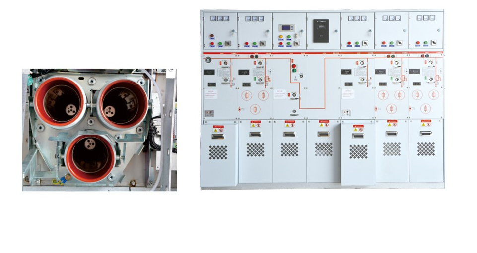
The cable connection compartment has large space, and the bushings are of standard design,實現 compatibility with all European standard cable plugs. Normally, each load switch unit can connect 1~3 outgoing circuits, with special designs capable of connecting 4~6 outgoing circuits. The vacuum circuit breaker unit can connect 1~2 outgoing circuits.
Uses internationally standard universal bushings (compliant with DIN47636 standard or American standards), making it convenient for users to choose corresponding cable accessories. Uses T-shaped front and rear cable plugs for connection, with a European-style bolt step-by-step tightening structure. The connection between the front plug and the bushing uses M16 bolts. The cable connection method can also use ordinary terminal blocks and heat-shrinkable sleeves.
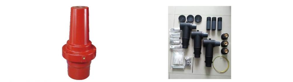

The load switch unit can be equipped with a T-shaped rear plug-type silicone rubber fully sealed metal zinc oxide arrester. When there are many cable circuits and space is insufficient, a π-shaped rear plug-type arrester can be used.
The fuse replacement for the SRM□-12 gas-insulated fully insulated fully enclosed ring main switchgear is direct and simple. The fuse is placed in an insulating tube, which is located inside the SF6 metal gas tank. This design has the following advantages:
◆ The fuse cover and sealing device are in the weakest part of the electric field.
◆ No conductive material can adhere to the fuse assembly.
◆ The part in the SF6 gas is completely protected.
◆ The fuse cover does not require additional insulation. The spring operating mechanism and linked tripping device ensure that the load switch opens automatically on all three phases when any one phase fuse operates.
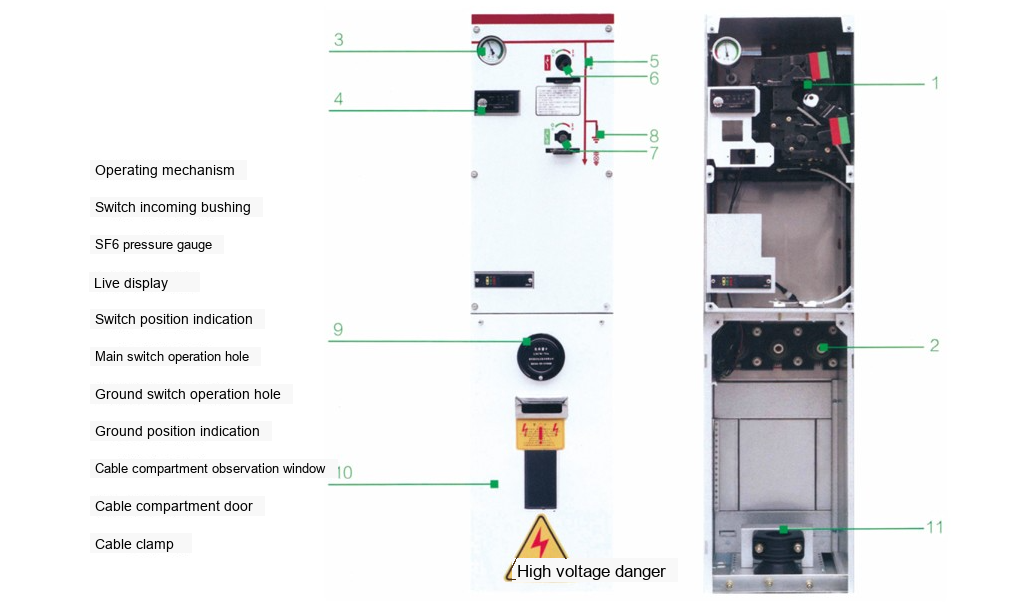
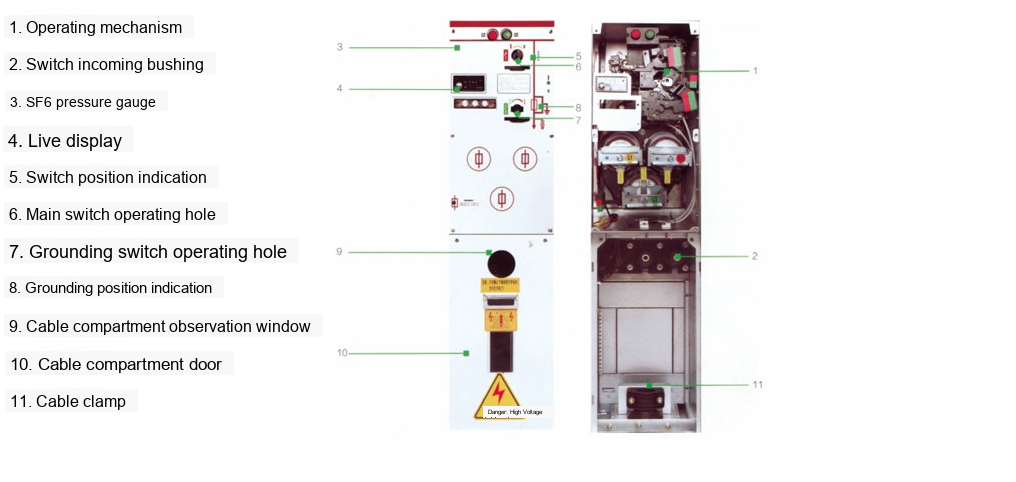
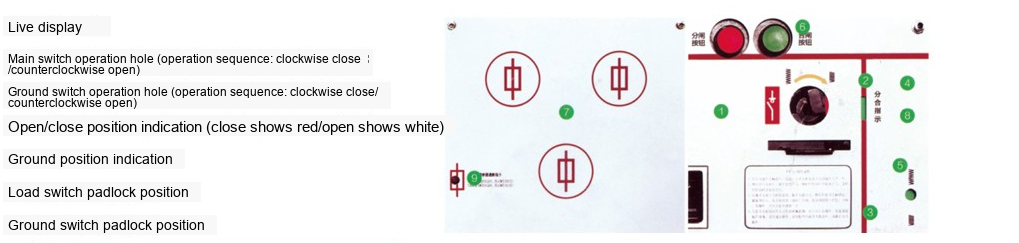
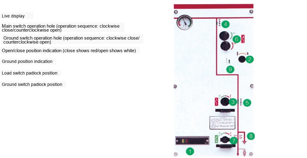
SRM□-12 Series Switch Panel Indications
① Live display device
② Main switch operating hole (Operation sequence: clockwise close / counterclockwise open)
③ Earthing switch operating hole (Operation sequence: clockwise close / counterclockwise open)
④ Open/closed position indicator (Closed shows red / Open shows white)
⑤ Earthing position indicator
⑥ Load switch padlock position
⑦ Earthing switch padlock position
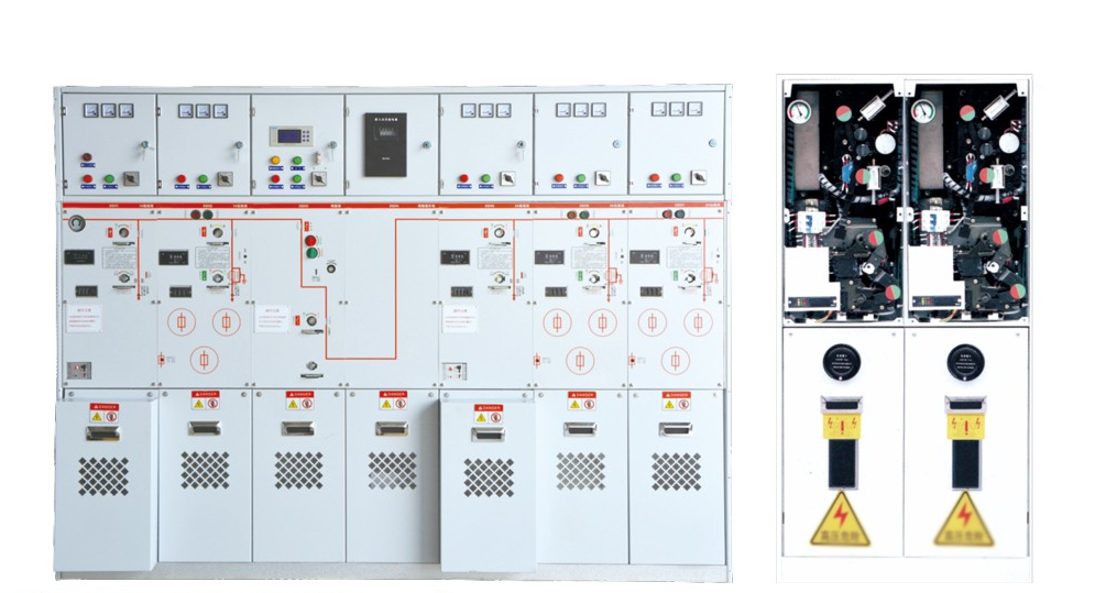
This switch can be divided into single unit, single unit with double bushing outgoing, two-unit, three-unit, four-unit, five-unit standard types, and types with side incoming bushings. It adopts a common SF6 gas tank structure, eliminating the need for external busbar connections between units. Therefore, the structure is relatively simplified, easy to install, and safer. Although it uses an integrated gas tank structure, each unit still has independent compartments. For more than six units, insulated busbar cabinet combination is used,可以实现 front-to-back or left-to-right combination. The cabinet type is the standard type with upper side bushing bushings.
Turn the switch operating handle counterclockwise half a turn, pull outward to replace the fuse. For installation, align with the hook position and turn clockwise.
SRM□-12 Switch Panel Indications
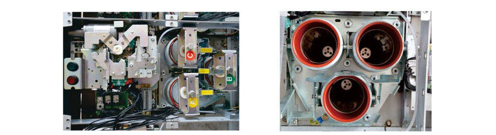
The combination unit is used for transformer protection up to 1250KVA capacity. This unit is equipped with insulating sleeves that can accommodate fuses. The insulating sleeves are placed inside the SF6 gas tank to further enhance insulation performance. When the earthing switch is closed, the lower side of the fuse is earthed simultaneously, achieving safe isolation of the upper side of the fuse from the power source, ensuring personnel safety during fuse replacement. To ensure that the operation does not cause single-phase operation after one phase fuse operates, this unit is equipped with a trip linkage mechanism. When the trip observation window shows red, it indicates that the tripping device has operated or the fuse has operated and tripped. This unit can be combined with other units to achieve loop network power supply.
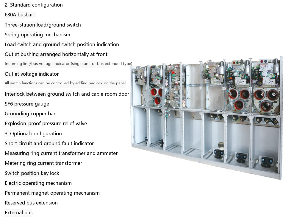
◆ 630A busbar ◆ Three-position load/earthing switch ◆ Spring operating mechanism ◆ Load switch and earthing switch position indication ◆ Front-mounted horizontally arranged outgoing bushings
◆ Incoming/busbar voltage indicator (single unit or busbar expansion type) ◆ Outgoing voltage indicator ◆ All switch functions can be controlled by padlock on the panel
◆ Interlock between earthing switch and cable compartment door ◆ SF6 pressure gauge ◆ Earthing copper busbar ◆ Explosion-proof pressure relief valve
◆ Short-circuit and earth fault indicators ◆ Ring-type current transformers for measurement and ammeters ◆ Ring-type current transformers for metering ◆ Switch position key lock
◆ Electric operating mechanism ◆ Permanent magnet operating mechanism ◆ Reserved busbar expansion ◆ External busbar
SRM□-12-F Switch Panel Indications
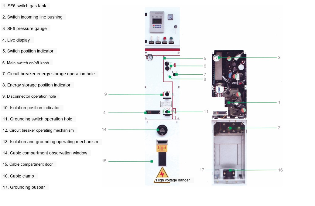
Uses a spring-type vacuum circuit breaker with a mechanical life of up to 10000 operations (fast protection action, opening time not more than 30ms),易于实现 selective coordination. Uses a three-position load disconnector. The vacuum circuit breaker and load switch are sealed together in an SF6 gas tank made of 3mm thick stainless steel plate. The entire system achieves full insulation, full sealing, and maintenance-free operation.
◆ 630A busbar ◆ 630A circuit breaker module ISM ◆ Controller CM (DC24V operating power)
◆ Three-position load disconnector ◆ External power supply, self-powered
Type microcomputer protection device ◆ Bushing-type protection CT ◆ SF6 pressure gauge
◆ Bushings compliant with DIN47636 standard ◆ Interlock between earthing and cable compartment door ◆ Vacuum circuit breaker switch position auxiliary contacts: 2NO+2NC
◆ Operating power (including PT for power supply, power module, backup battery)
◆ Connection busbar
◆ Current transformers for measurement and ammeters
◆ Auxiliary contacts: Load disconnector position 2NO+2NC, Earthing switch position 2NO+2NC
◆ Permanent magnet mechanism,可以实现 fast opening and closing of circuit breaker, used for section circuit breaker switchgear or incoming switchgear
SRM□-12-V Switch Panel Indications
Accessory Overview
SRM□-12 Fully Enclosed Fully Insulated Gas-Filled Ring Main Switchgear|10kV SF6 Gas-Insulated Switchgear Manufacturer

Telephone

Online Service

Follow Us


TikTok

Back to Top


