
High Voltage Complete Switchgear Cabinet
Product Title
Product Details
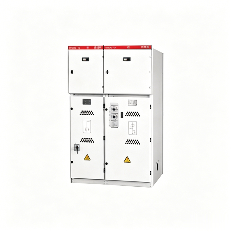
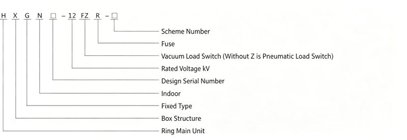
The HXGN□-12 AC metal-enclosed switchgear (referred to as ring main unit) is an AC high-voltage complete device with a rated voltage of 12kV and rated frequency of 50Hz. It is mainly used in three-phase AC loop networks, terminal distribution networks, and industrial power equipment for receiving, distributing electric energy, and providing protection. It is also suitable for installation in compact substations.
Complies with GB3906 "3.6~40.5 AC Metal-enclosed Switchgear and Controlgear" and meets the requirements of IEC298 "AC Metal-enclosed Switchgear and Controlgear". It also has "five-prevention" interlocking functions.
◇ Ambient temperature upper limit +40C, lower limit -25C;
◇ Altitude not more than 1000m;
◇ Relative humidity daily average not more than 95%, monthly average not more than 90%;
◇ Installation site free from fire, explosion hazards, and severe vibration;
◇ Ambient air free from significant contamination by corrosive or flammable gases, water vapor, and conductive dust;
◇ Fully assembled structure, lightweight and aesthetically pleasing, can be combined and installed arbitrarily,易于 unlimited expansion and extension.
◇ Can be equipped with FN12-12 air-pressure load switch and combination units, or FZN25-12 vacuum load switch and combination units. Small size, maintenance-free, three-phase linked structure, with clear isolating gaps.
◇ The load switch and combination unit have flexible installation methods, can be mounted on left/right side, front, or inverted (FZN25 cannot be inverted).
◇ Can be operated manually and electrically, with remote control capabilities.
◇ Equipped with comprehensive and reliable mechanical interlocking devices, fully achieving "five-prevention" functions.
a. When the load switch is closed, the earthing switch cannot be closed, and the front door cannot be opened;
b. When the load switch is open, the earthing switch can be closed. When the earthing switch is closed, the front door can be opened;
c. When the earthing switch is closed, the load switch cannot be closed, and the front door can be opened;
d. When the earthing switch is open, the load switch can be opened/closed, and the front door cannot be opened;
e. For bottom cable incoming, when the incoming line is energized, regardless of whether the load switch is in the closed or open position, the electromagnetic lock controls the front door, preventing it from being opened (except for emergency unlocking with a special key).
◇ The load switch uses a protective insulating shutter or transparent insulating cover to shield live contacts, ensuring personal safety.
◇ Front operation and maintenance, can be installed against the wall.
◇ The front door is equipped with an observation window for clear viewing of the internal component working status.
| No. | Name | Unit | FN12-12 | FZN25-12 |
|---|---|---|---|---|
| 1 | Rated Voltage | kV | 12 | |
| 2 | 1min Power Frequency Withstand Voltage | kV | Earth and phase-to-phase 42; Isolating gap 48 | |
| 3 | Lightning Impulse Withstand Voltage (Peak) | kV | Earth and phase-to-phase 75; Isolating gap 85 | |
| 4 | Rated Frequency | Hz | 50 | |
| 5 | Rated Current | A | 630 | |
| 6 | Electrical Life at Rated Current | times | Not less than 100 | |
| 7 | Breaking Capacity of No-load Transformer | KVA | 1250 | |
| 8 | Rated Thermal Stability Current | kA/S | 20/4; Earthing switch 20/2 | |
| 9 | Rated Dynamic Stability Current (Peak) | kA | 50 | |
| 10 | Rated Short-circuit Making Current (Peak) | kA | 50 | |
| 11 | Fuse Rated Current | A | 125 | |
| 12 | Rated Transfer Current | A | 870 | |
| 13 | Rated Short-circuit Breaking Current | kA | 20 | |
| 14 | Fuse Model Used | S□LAJ-12 | ||
| 15 | Mechanical Life | times | 2000 | 10000 |
| 16 | Auxiliary Circuit 1min Power Frequency Withstand Voltage | kV | 2 | |
| 17 | Electric Operating Mechanism Operating Voltage | V | AC/DC 220; 110 | |
| 18 | Protection Level | IP2X | ||
| Load Switch | ||||
| Combination Unit | ||||
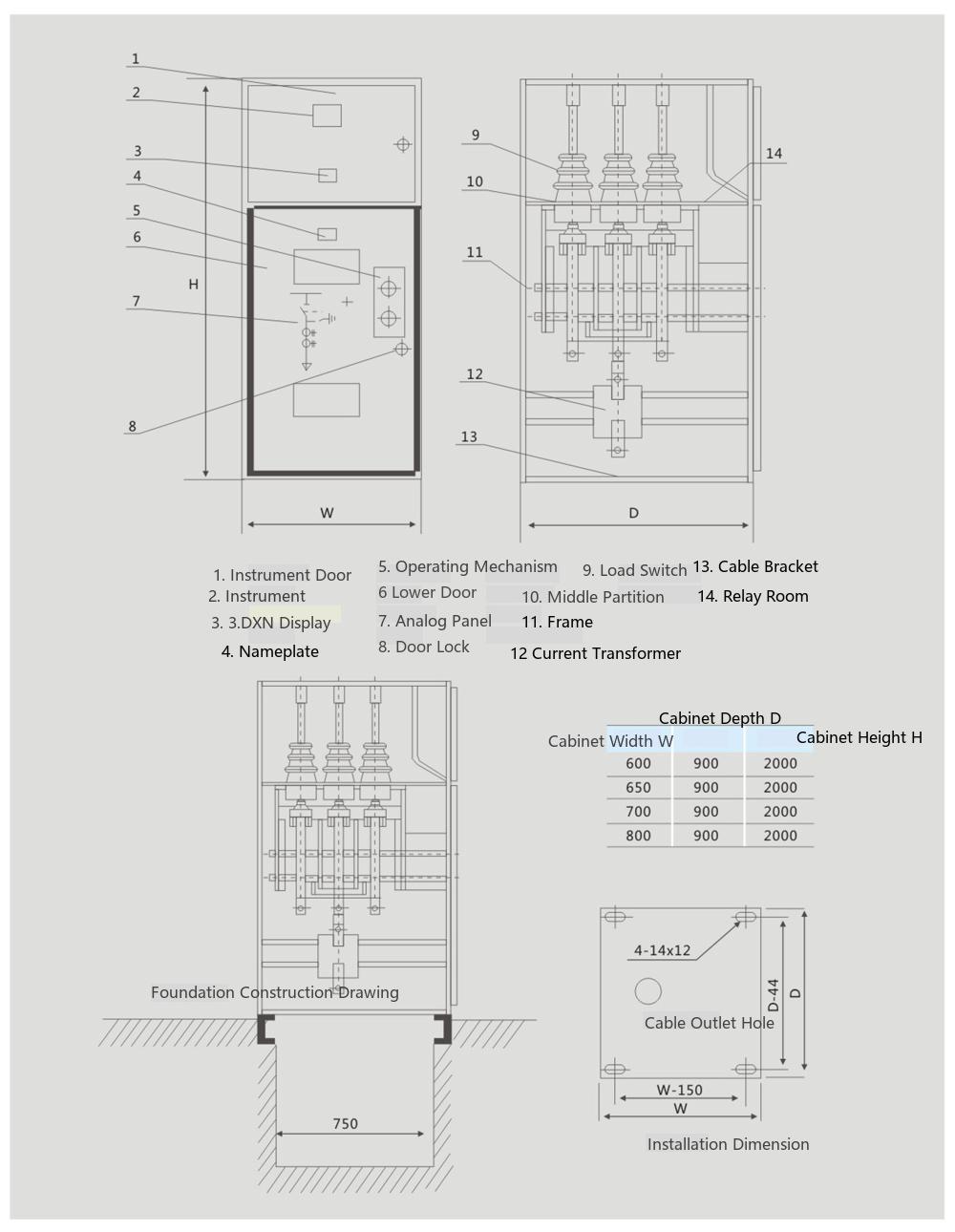
◇ Refer to Figure 1 for external dimensions and installation foundation. The foundation channel steel should protrude 1-3mm above the ground. Unevenness should not exceed 1.5mm per meter, and not exceed 5mm over the entire length.
◇ Place the switchgear on the foundation in order and adjust the installation position. Then fix with M12 bolts or spot welding. Use M8 bolts to tighten between cabinets.
◇ Remove the rear cover plate to install the main busbar and primary cables. The contact surfaces of the terminals should be cleaned and coated with neutral petroleum jelly. After installation, remember to seal the primary cable holes.
◇ Connect the cabinet-to-cabinet earthing busbar to form a continuous connection along the row of switchgear. Check for missing grounding points and ensure the grounding circuit is continuously conductive. The grounding resistance should not exceed 1Ω.
◇ Install secondary cables. The cables enter from the bottom front of the cabinet, run along the side wall into the relay room, and connect to the terminal blocks; or enter the relay room from the secondary small busbar on the top of the cabinet. After installation, seal the cable holes.
◇ Clean dust and debris inside the cabinet.
According to the order requirements, check whether the models and specifications of the electrical components installed in the cabinet match; check whether fasteners are loose; check whether primary and secondary wiring is correct; operate the load switch, earthing switch, and mechanical interlocking 3~5 times to ensure flexibility and no jamming, and that the interlocking meets the "five-prevention" requirements. Then apply lubricating grease to the mechanical moving parts.
Check the insulation level and circuit resistance of the switchgear, and the mechanical characteristics of the load switch according to the manual and factory test report. The test results should be consistent with or close to the factory test report.
Power-on operation: Only when the cabinet door is closed and locked, and the earthing switch is operated to the "open" position, can the load switch be operated to the closed position (if there is no earthing switch, set the interlocking mechanism to the "open" position).
Power-off operation: Only when the load switch is in the isolated position after opening can the earthing switch be closed. Only when the earthing switch is in the closed position can the cabinet door be opened (if there is no earthing switch, set the interlocking mechanism to the "closed" position).
Note: When maintaining the incoming cabinet, cut off the incoming power, open the load switch, check the live display on the cabinet to confirm no power, open the cabinet door, and hang the grounding wire before performing maintenance.
◇ Users should regularly maintain and inspect the switchgear, generally every six months or one year;
◇ Clean dust from all parts, especially accumulated dust on the surfaces of insulating parts;
◇ Check mechanical moving parts and regularly apply lubricating grease to keep them flexible and reliable;
◇ Check whether electrical contact parts are in good condition, whether there is overheating, and whether the grounding circuit is continuous;
◇ Check whether fasteners are tightened.
◇ When maintaining the incoming cabinet, first cut off the upstream power, open the load switch, check the live display to confirm no power, open the door, hang the grounding wire, and then perform maintenance.
◇ When a fuse operates due to a short circuit, regardless of whether one or two fuses operate, all three must be replaced.
◇ Carry out maintenance according to the instruction manuals of the main components.
Our company provides the following documents and accessories upon delivery:
◇ Delivery list
◇ Product certificate and factory test report
◇ Instruction manual
◇ Relevant electrical drawings
◇ Instructions for main components
◇ Cabinet door keys, operating handles, and spare parts specified in the contract.
The following technical information should be provided when ordering:
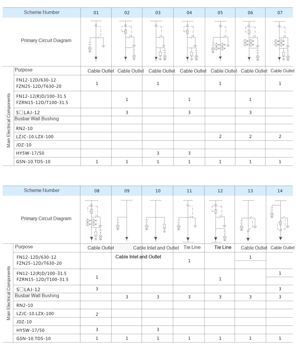
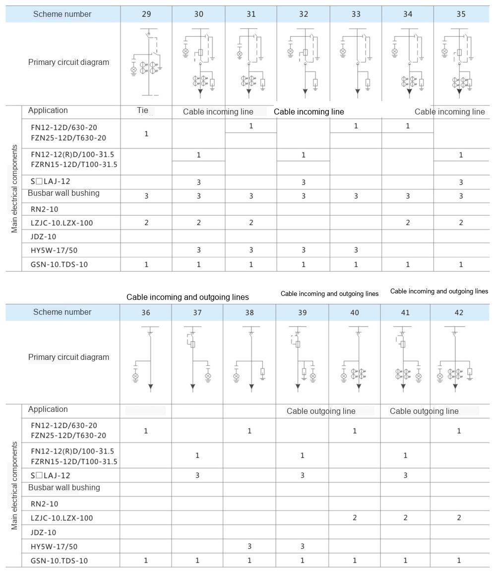
◇ Main wiring scheme number, purpose, single-line system diagram, rated voltage, rated current, rated short-circuit breaking current, distribution room layout plan, and switchgear arrangement diagram;
◇ Requirements for switchgear control, measurement, and protection functions, as well as requirements and schematics for other interlocking and automatic devices;
◇ Models, specifications, and quantities of main electrical components inside the switchgear;
◇ If the switchgear is to be used in special environmental conditions, detailed description should be provided when ordering;
◇ Other special requirements should be detailed in writing and discussed before ordering.
HXGN17-12 AC Metal-enclosed Switchgear|10kV/630A Ring Main Unit Manufacturer Direct Sales

Telephone

Online Service

Follow Us


TikTok

Back to Top


