
High Voltage Complete Switchgear Cabinet
Product Title
Product Details
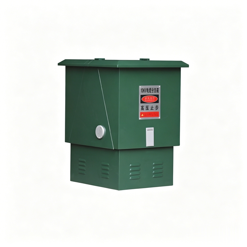
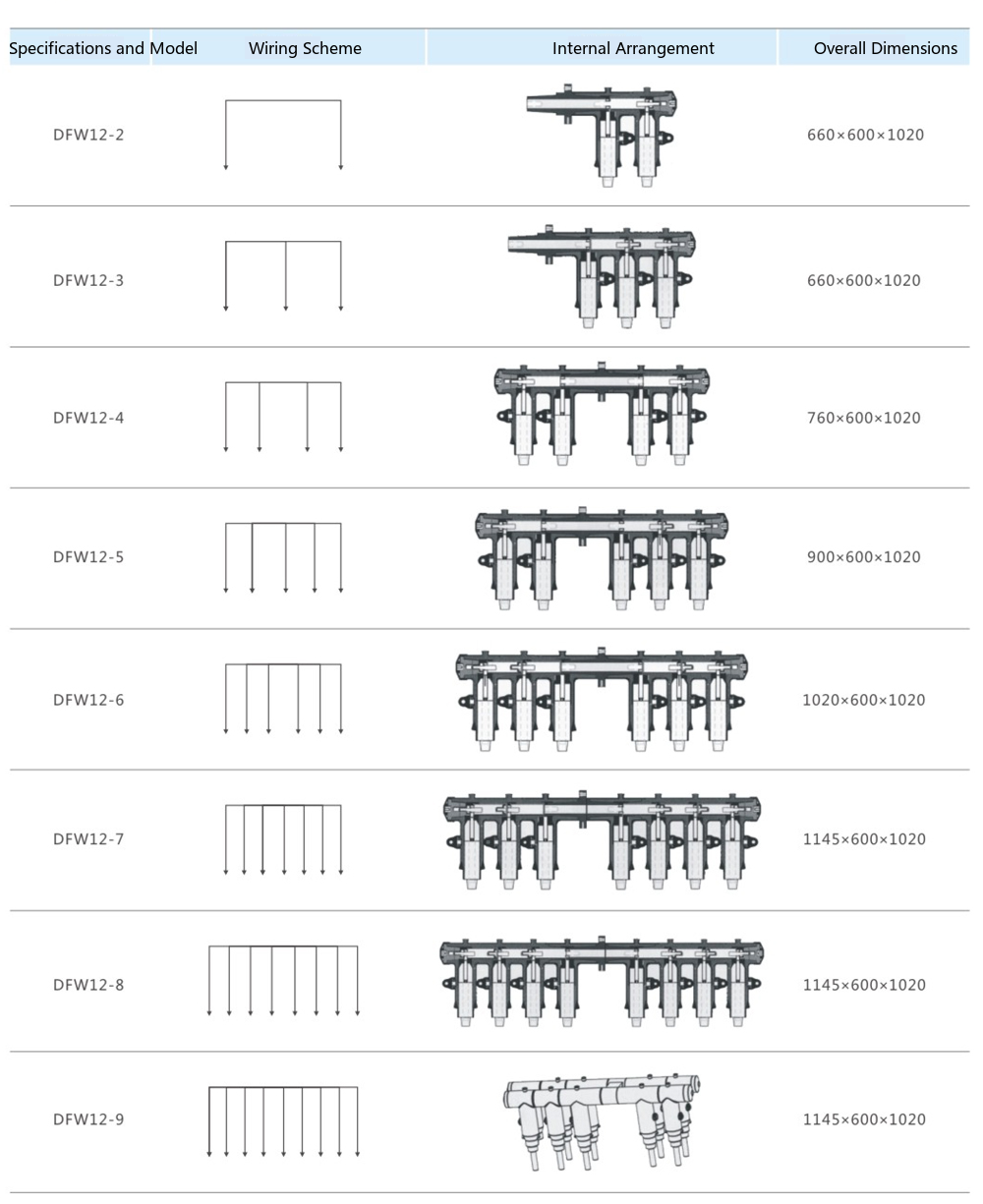
The DFW-12 high-voltage cable branch box is a cable-based engineering device widely used in power distribution networks in recent years. Its main features are double-sided doors, using feed-through bushings as the connecting busbar, with advantages such as small length, clear cable arrangement, and no need for large-span crossings of three-core cables. The cable connectors used comply with the DIN47636 standard. Generally, 630A bolted fixed connection cable connectors are used. The DFW-12KV/630A high-voltage cable branch box adopts a fully sealed and fully insulated structure, with flexible and expandable incoming and outgoing lines, and a protection level above IP33. It is the core node device for cable line tapping and transfer in 10kV distribution networks.
Environmental Conditions for Use
Technical Parameters
| Rated Voltage | 12kV |
| Rated Current | 630A |
| Dynamic Stability Current | 50kA/0.3s |
| Thermal Stability Current | 20kA/3s |
| 1 Minute Power Frequency Withstand Voltage | 42kV |
| 15 Minute DC Withstand Voltage | 52kV |
| Lightning Impulse Withstand Voltage | 105kV |
| Enclosure Protection Level | IP33 |
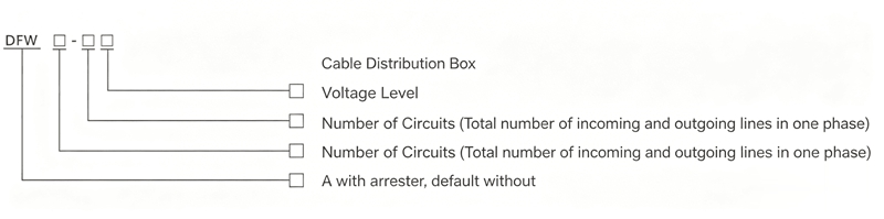
Ordering Code Description
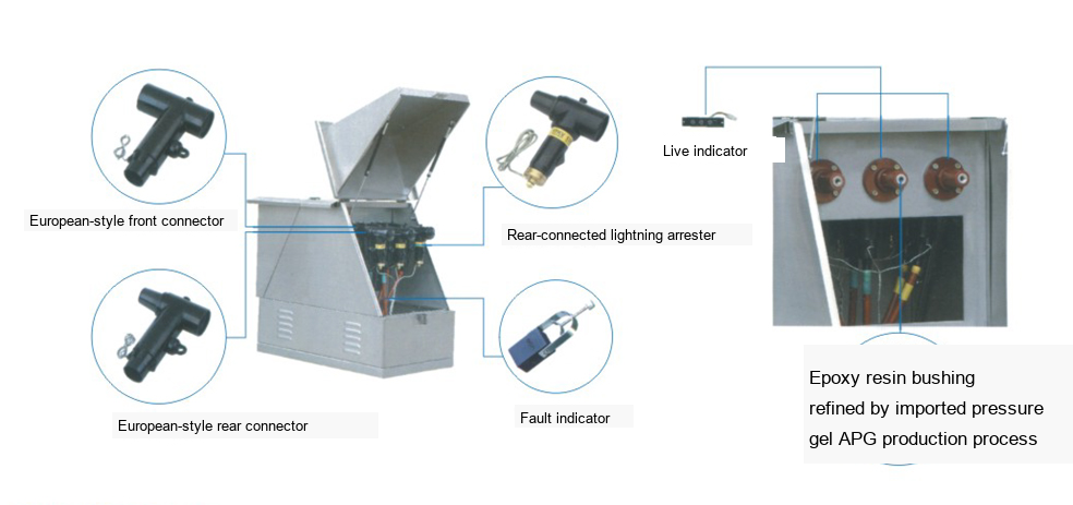
European-Type Cable Distribution Box Structure Example Diagram
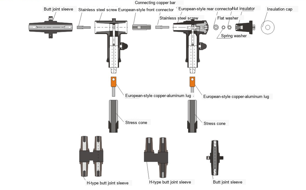
If the site is limited and cannot accommodate a cable distribution box, the cable connectors can be directly combined to form multiple cable branches (without the need for a busbar, connection method shown on the right) and placed in cable trenches or other locations.
Example 1: Four-way incoming/outgoing, each phase consists of two European-type front connectors and two European-type rear connectors, with one European-type feed-through bushing connecting them in the middle. The ends of the European-type rear connectors are sealed with insulators and semi-conductive end caps. See the example figure below:

Example 2: Two incoming, three outgoing
Each phase consists of three European-type front connectors and two European-type rear connectors, connected in the middle by European-type feed-through bushings. The ends of the European-type rear connectors are sealed with insulators and semi-conductive end caps. See the example figure below:

Note: Cable branches can be arbitrarily expanded or reduced according to needs, and can be housed in an enclosure or directly buried in cable trenches.
Cable Plug Installation Diagram
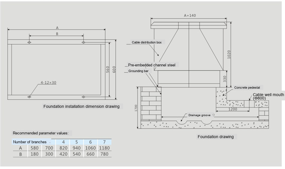
European-Type Cable Distribution Box Foundation Diagram
DFW-12KV/630A High-Voltage Cable Branch Box | 12kV Power Distribution Network Cable Tapping Device

Telephone

Online Service

Follow Us


TikTok

Back to Top


